s14clock
S14 Clock
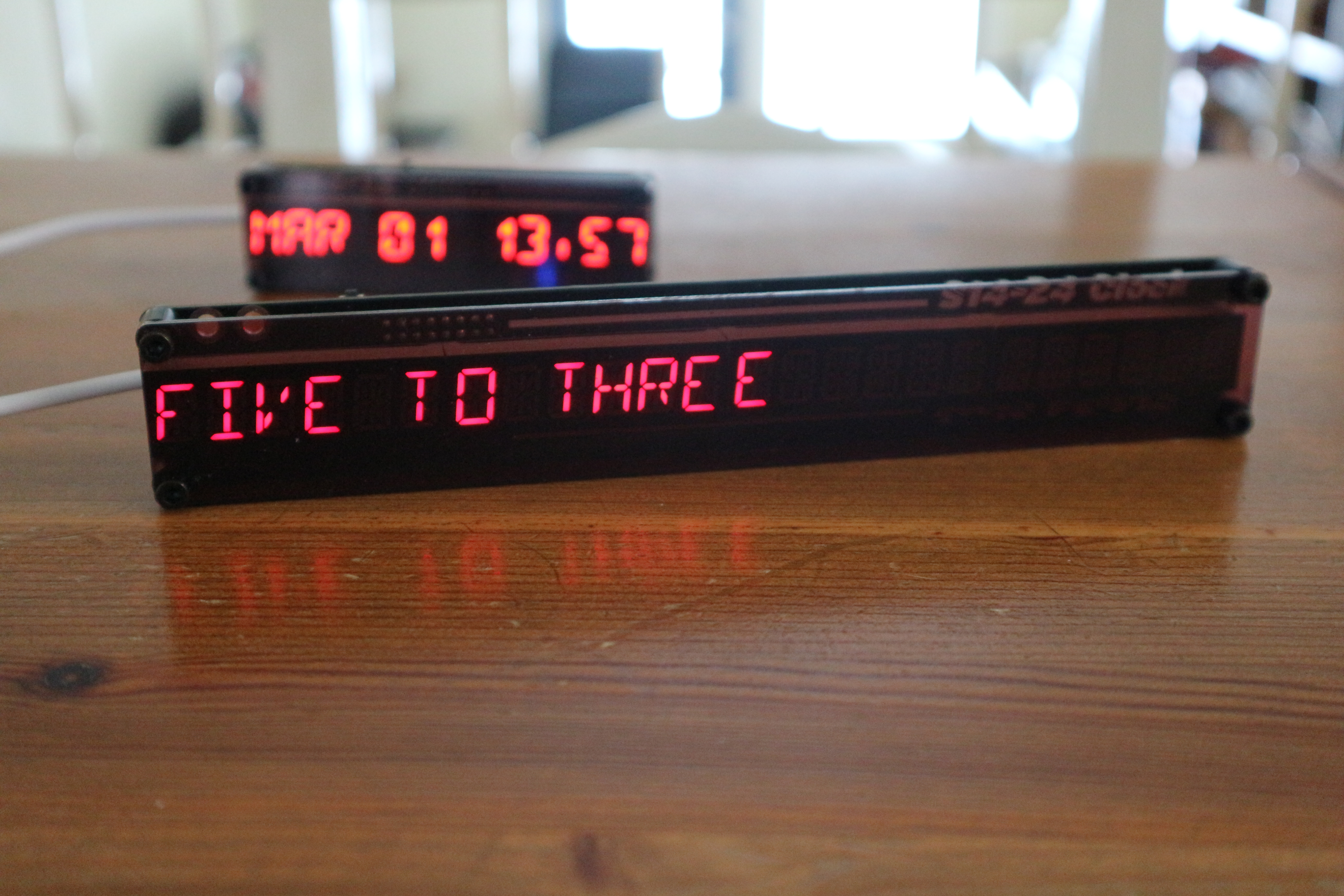
Bar shaped, web synchronized word clock featuring 24 or 12 characters, 14 segment LED display
2023-06-07 V3 hardware (24 characters) released, 74HC154 eliminated. New circuit design adds charliplexing to led multiplexing to simplify design. No more SMD to solder makes a more robust kit.
Description
This is a web synchronized clock featuring 14 segment LED displays, allowing spelled word time display options, plus various numeric character sets.
The S14Clock is available for purchase from store139 in Tindie.
If you are building this project, there are additonal tips in the project wiki page.
Github repository, my github repository
Firmware Installer click here.
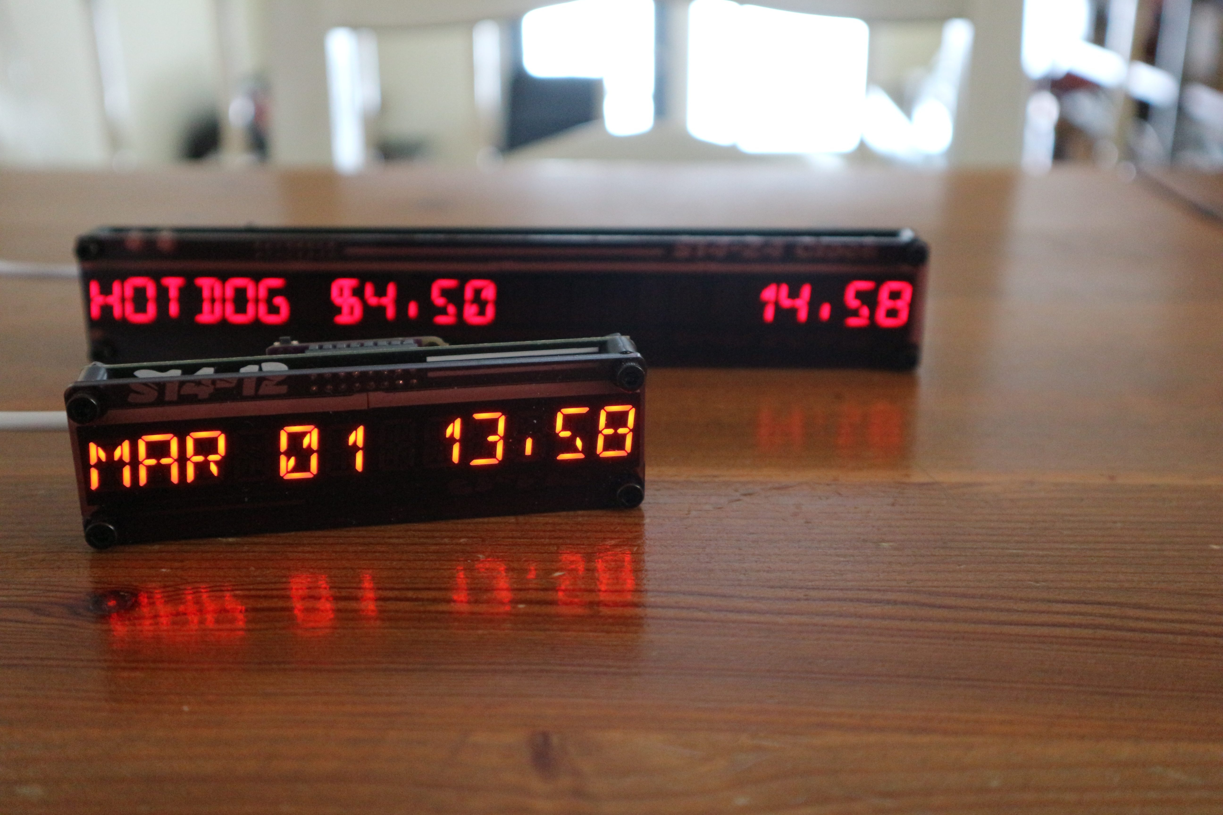
Two versions of 12 (S14-12) and (S14-24) 24 characters were created, with same functionality. The clock offers various display format and optons. It can also be used as an internet display, accepting messages via a web page.
A single tactile button is used to advance one of the eight present display formats / messages. The same button when pressn-hold allows cycling between various display transition effects.
A countdown timer can also be activated via double tapping the button. Setup is done via a web interface that allow for 8 preset display formats / messages.
Main Features
- Web based WIFI setup, upon initial usage.
- Web based configuration, to preset up to 8 display formats or messages.
- Date time formats via strftime() c library standard.
- Ad-hoc message via web page posting.
- Synchronize date time via ntp.org time server.
- Various setting including automatic cycling of messages, alternate numeric symbols, etc.
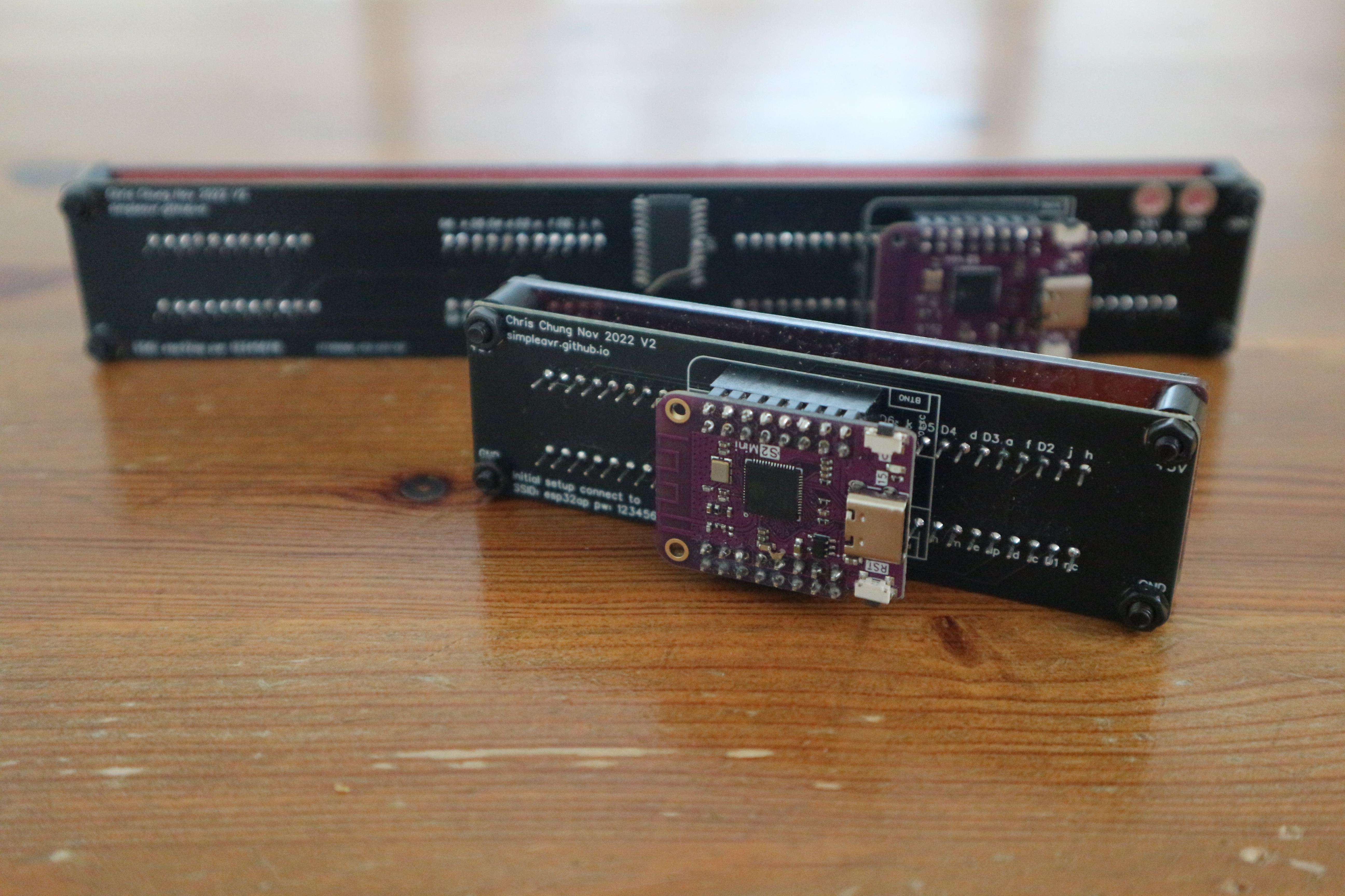
- Employs ESP32 S2 Mini, with open source code via github.
- S14-24 24 characters dimension 200mm x 32mm x 30mm (approx. 8” x 1-1/4” x 1-1/4”)
- S14-12 12 characters dimension 100mm x 30mm x 30mm (approx. 4” x 1-1/4” x 1-1/4”)
Technical Details
- Employs Arduino ESP32 AutoConnect library for entering WIFI credentials.
- Full use of ESP32 S2 Mini IO pins to perform LED multiplexing and charlieplexing.
- Access of IO registers directly and timer interrupts for efficient multiplexing.
Initial Setup
The device must be connect to your home network in order to gain time server access via the internet. You will need to provide your home network name (SSID) and password via the ESP32 AutoConnect library.
Power up your S14Clock, you should see the message “CONNECTING” after a brief display checkup.
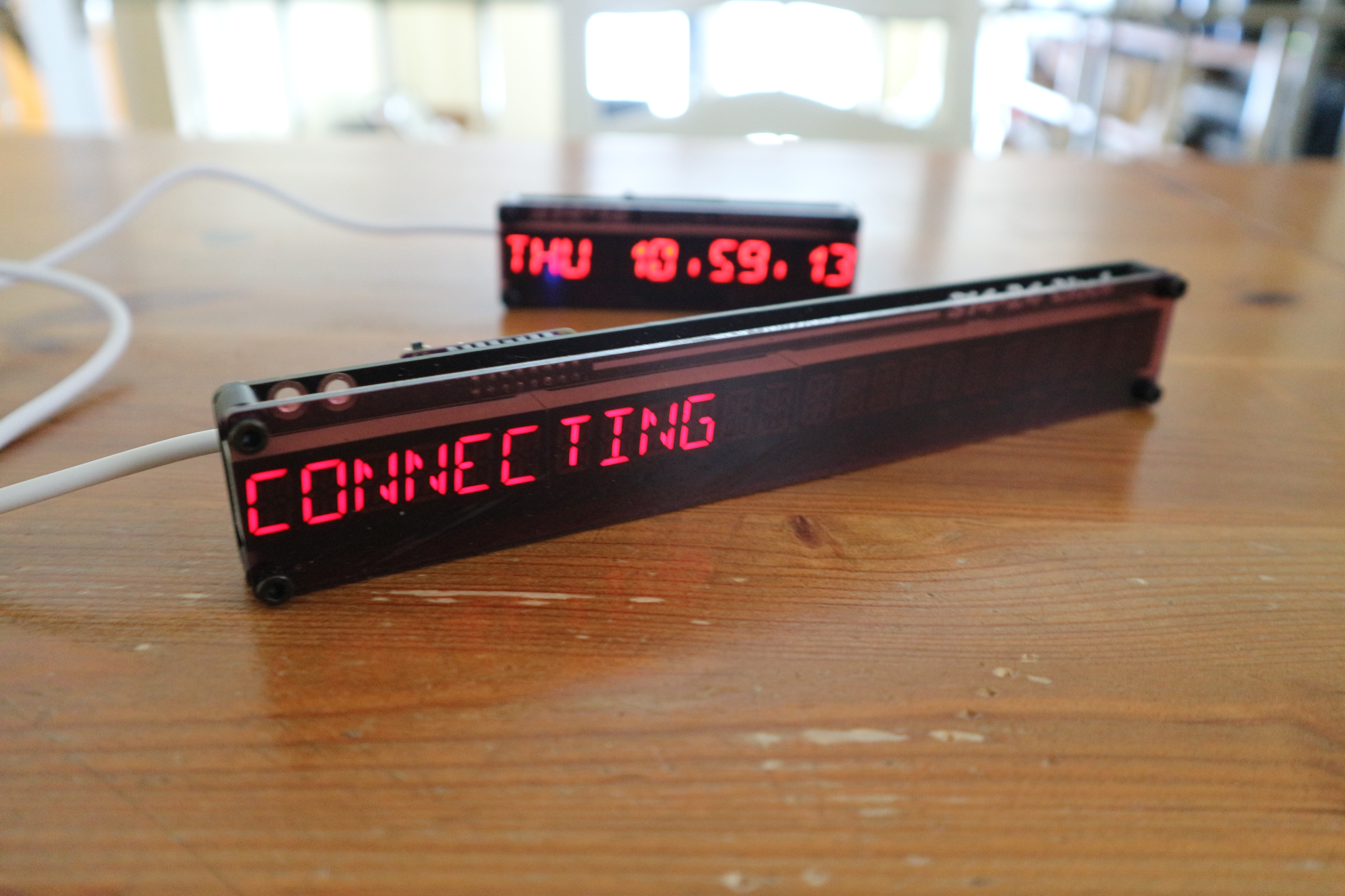
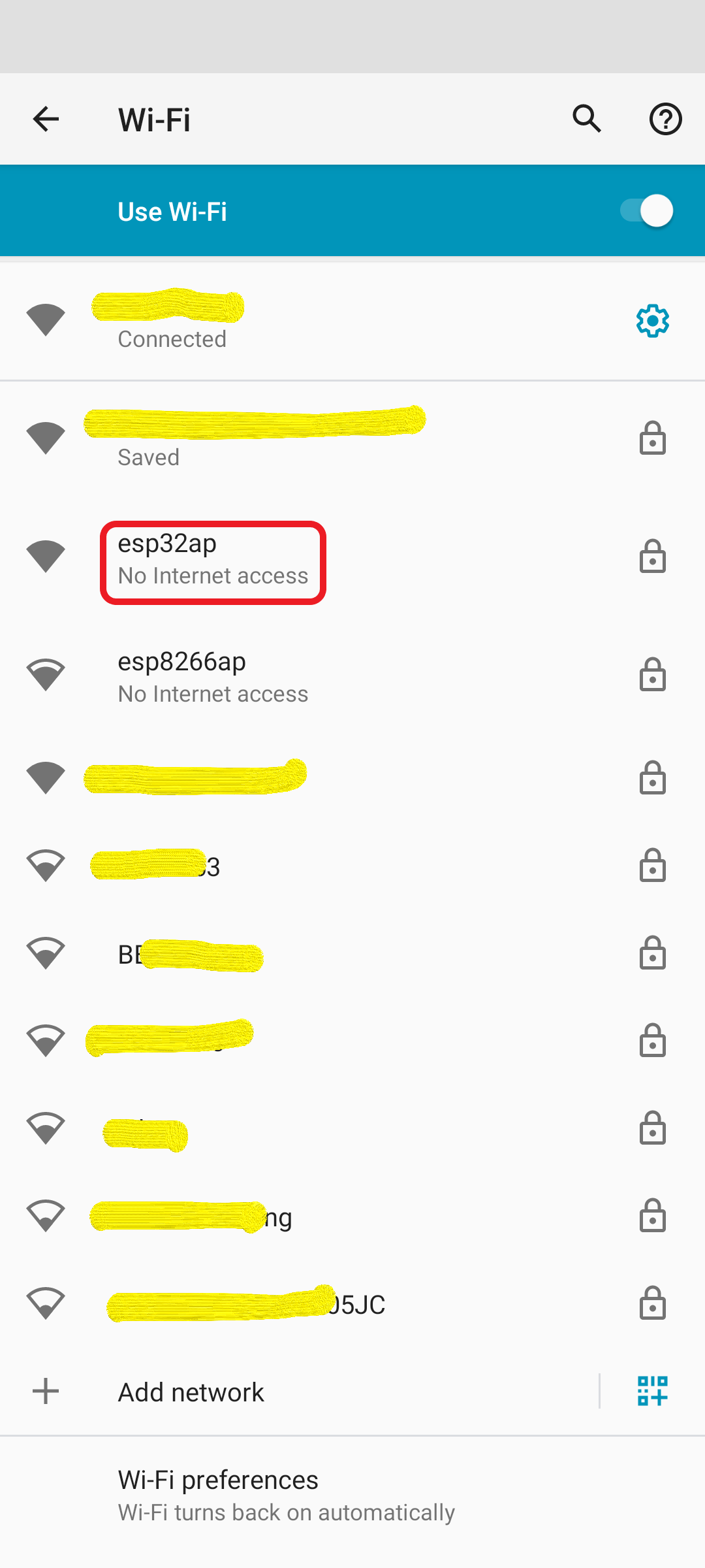
Use your phone or computer and locate the AP with SSID “ESP-??????”, connect with password “12345678”.
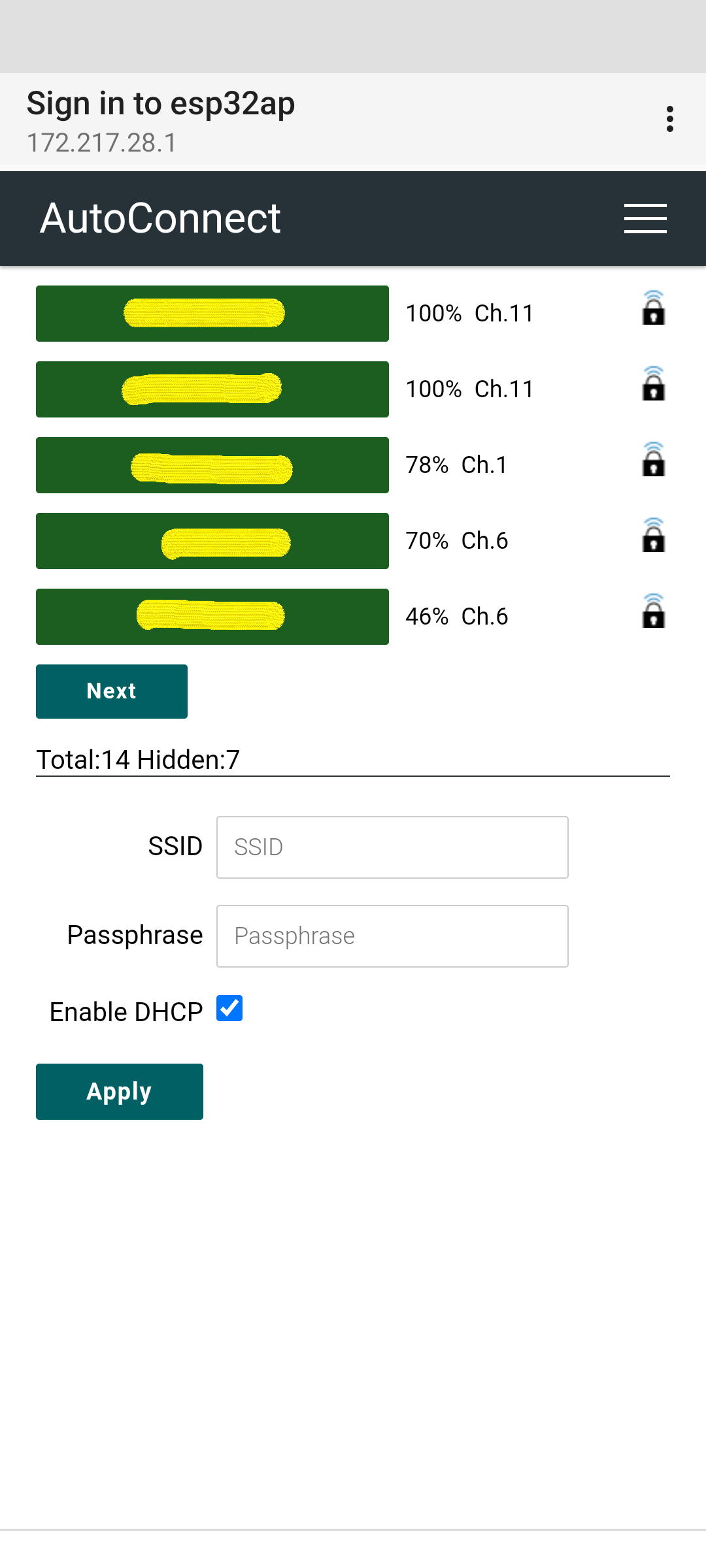
Choose from the “3-bar” menu (top right) “Configure new AP” and select your home network.
Enter your home network WIFI credentials and hit “Apply” button.
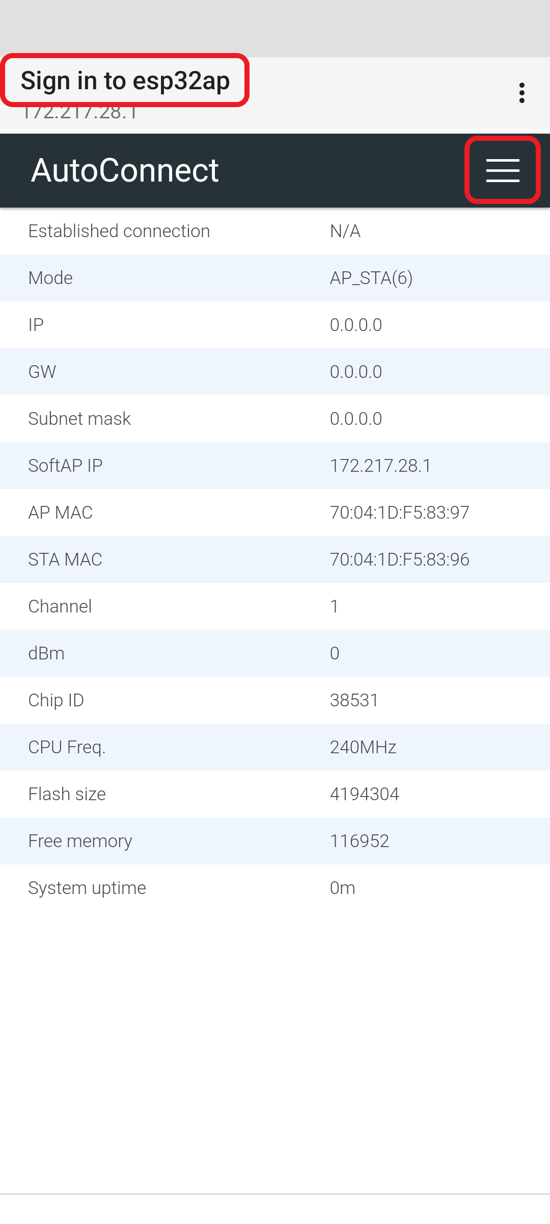
Your S14Clock should connect to your home network and will start to work after showing it’s IP address briefly. You may need to reset the S14Clock via the bottom hardware reset button.
Application Notes (Clock Unit)
The S14Clock make use of the button on the ESP32 module for local functionalities, at the back of the clock unit, there are 2 buttons, the button marked ‘RST’ is a power reset button. The button marked ‘0’ is the application button;
- Single press advances (cycles) the 8 preset display format / messages.
- Press-n-hold advances the display transition effect, subsequent presses cycles to the next transition effect.
- Double press in quick succession starts the countdown / countup timer with the present countdown / countup message. Double presses again when clock unit is already in countdown mode will advance the countdown time. Single key press cancels the countdown timer.
Application Notes (Web Server)
Upon power up the S14Clock will show it’s IP address briefly. The S14Clock runs a web server for configuration and customization. Enter the IP address via a browser to access the appliation server.
The primary buttons at the top of the page serves the following purposes;
- Count Down turns the display into a countdown timer, additional press on this button advances the countdown time.
- Advance Display cycle to the next display format, as setup via “Display Content” entries.
- Reset Configuration resets S14Clock to preset default configuration values.
- Reset WIFI forget current WIFI credentials, next power up will require WIFI setup again.
- Use button to confirm use of system discovered Posix TZ (timezone) configuration.
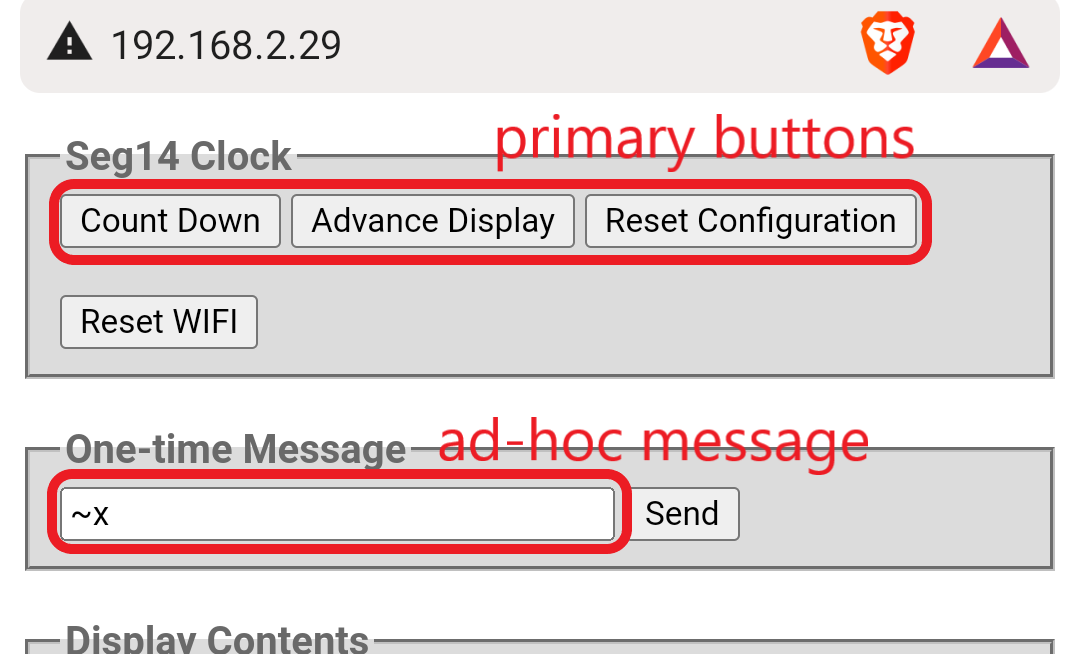
Ad-hoc messages can be entered and send to the S14Clock display. If entered text is prefixed with ~x or ~X, message will expire in 10 or 60 seconds and clock will return to previous display content.
Eight sets of display contents (left plus right aligned text and tokens) can be configured, along with checkboxes to turn them on and off. The “on” contents will be cycled through the cycle / advance display button.
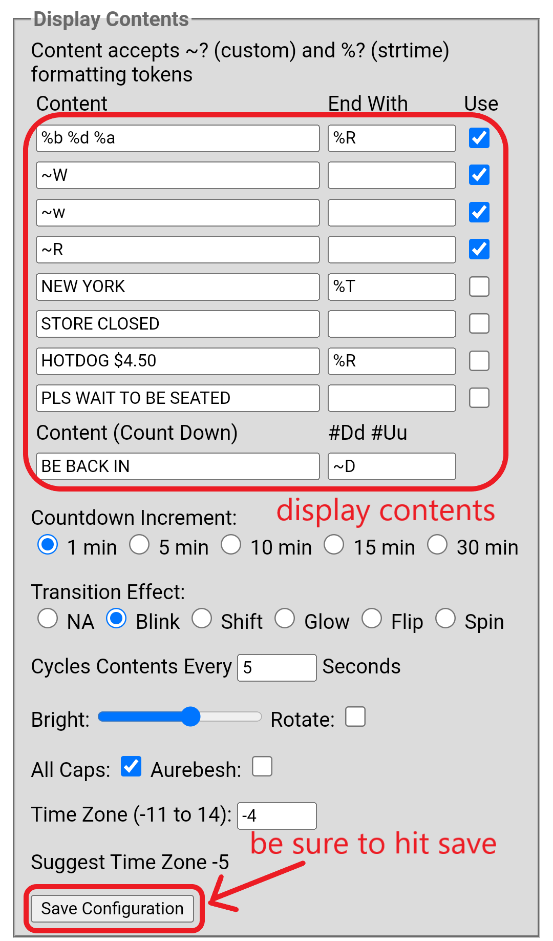
A separated countdown content display set is used specifically for countdown function.
Optional Alternate NTP Server entry if you want a different or local NTP server setup.
Posix TZ entry, if entered, allows Posix Time Zone string to describe GMT offset, daylight saving time details, this can be populated automatically from the Use button at the top of the page after user verify the zone discovery result is reasonable.
Tokens are used to substitute current date time elements and also font used. Their usage can be found in the “Format Control” section below.
The rest of the configuration parameters are self explainary. Countdown Increments, Transit Effects, Cycle Seconds (0 for no content cycling), Brightness, Rotate (when display is turn upside down), All Caps, Auresh (special font) and Time Zone.
The Format Control section explains how tokens can be used to display various date time elements, plus other special features in S14Clock, builtin features are in the format of tilde + code (ex. ~W), strtime() tokens in the format of percent + code (ex. %H), strtime() is a C language function for date time formatting.
Change of Time Zone, after clicking on the ‘Save’ button, will also require a hardware reset on the clock unit to take effect. This is a failsafe setup, as the Posix TZ setting should already cover the GMT offset and provide daylight saving time information.
Startup Options
Upon startup or hardware reset, the clock unit will show briefly various messages, pressing button 0 (of the S2 Mini board) at various stages will allow for certain operations.
Upon power-up, display will show “000000000000…” for 0.7 seconds, followed by “****…” for 0.4 seconds, it will then show the firmware and hardware versions for 2 seconds.
During the show of “000000000000…”, press and hold button 0 will reset the WIFI credentials of the clock unit, and upon next reset the clock unit will be placed in strict setup mode only, and will not search for WIFI network setup previously.
During the show of versions, “FWx.xx HWxxx”, press button 0 will force the clock unit to enter a burn-in mode, and the clock unit will operate the display mechanism without WIFI and NTP connection.
Firmware Update
Potential bug fixes and feature enhancements will be provided in my github repository.
You need a modern / recent browser that supports Web-Serial-API to use the Firmware Installer.
Components and Assembly
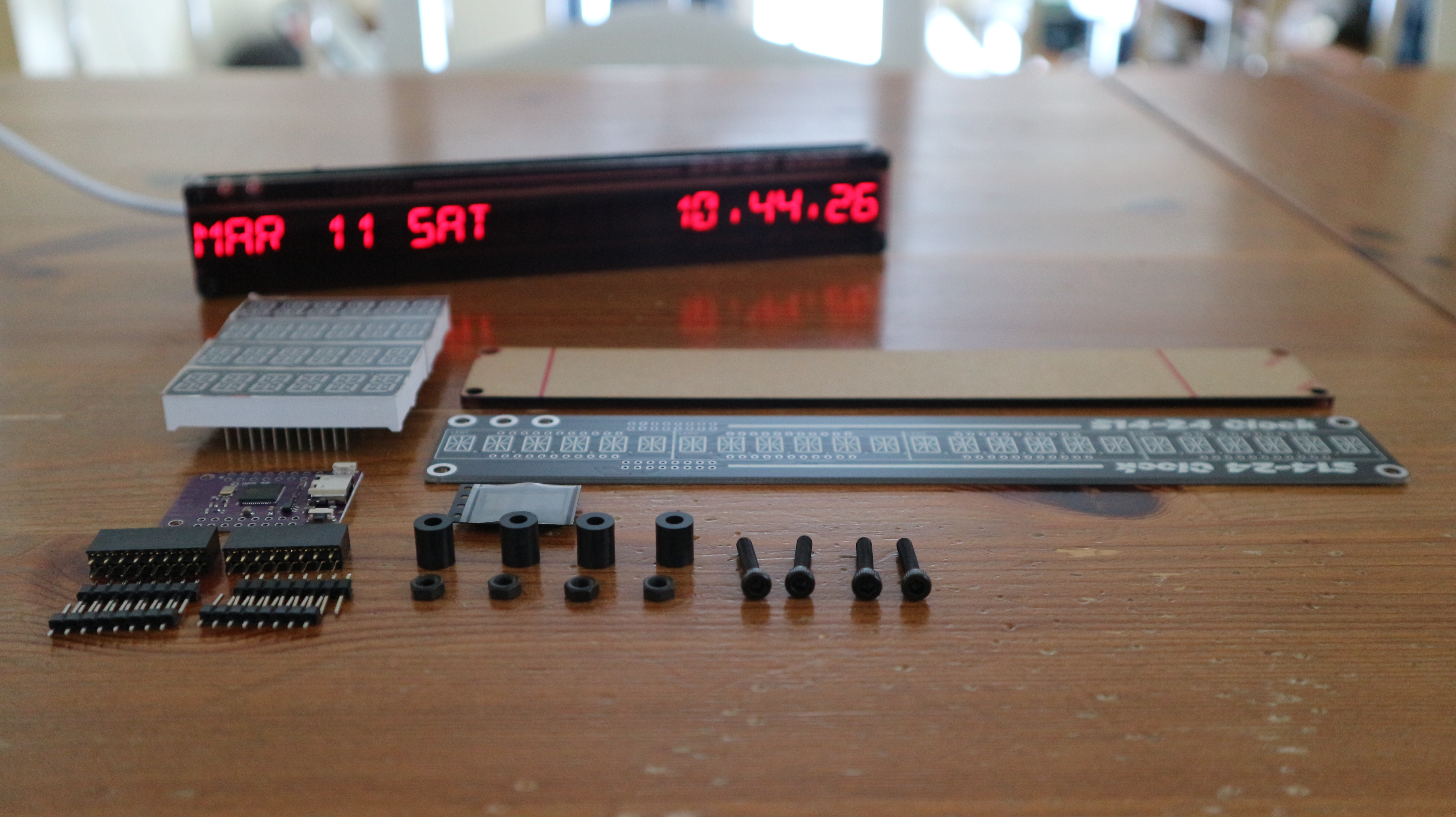
- 1× ESP32 S2 Mini module, w/ male headers
1x 74HC154D 4-16 line decoder (not needed for S14-12)- 4x 3692AS common cathode 14 segments 6 digits LED module (2x for S14-12)
- 2x 8x2 female header
- 4x M3 16mm steel screws
- 4x M3 steel nuts
- 4x M3 8mm black acrylic spacers
- 1x laser cut acrylic filter / front panel
Component placement follows printed circuit board footprints. As all components are symmetrical, please observe orientation when placing. Apart from that the soldering process is straightforward.
Schematic and Source Code
           (S14-24V3 Clock) **latest design, replaces S14-24, eleminates 74HC154**
           ESP32 S2 MINI
         -----------------                             2x 3692AS LED Displays
        |                 |                  _____________________________________
        |           row 0 |---------------->|D1  ___                         ___  |
        |           row 1 |---------------->|D2 |\|/|    _________________  |\|/| |
        |           row 2 |---------------->|D3  - -   ___________________   - -  |
        |           row 3 |---------------->|D4 |/|\|                       |/|\| |
        |           row 4 |---------------->|D5  ---                         ---  |
        |           row 5 |---------------->|D6  A B C D E F 1 2 H J K L M N dp   |
        |                 |                  ----|-|-|-|-|-|-|-|-|-|-|-|-|-|-|----
        |                 |                  ____|_|_|_|_|_|_|_|_|_|_|_|_|_|_|____
        |           row 6 |---------------->|D1     ___ a                         |
        |           row 7 |---------------->|D2   f|\|/|b (hjk)                   |
        |           row 8 |---------------->|D3     - - g G                       |
        |           row 9 |---------------->|D4   e|/|\|c (nml)                   |
        |           row 10|---------------->|D5     === d                         |
        |           row 11|---------------->|D6                                   |
        |                 |                  ----|-|-|-|-|-|-|-|-|-|-|-|-|-|-|----
        |                 |                      | | |                     | |
        |           com 0 |----------------------+ | |                     | NC
        |           com 1 |------------------------+ |  /................/ |
        |           com 2 |--------------------------+                     |
        |           .   ..| ....     similar to all common lines     ..../ |
        |           .   ..|    ....                                        |
        |           com 13|------------------------------------------------+
        |                 |    **digits become segments, and segments become digits in this charliplexing configuration**
        |                 |                            2x 3692AS LED Displays
        |                 |                  _____________________________________
        |           com 0 |---------------->|D1  ___                         ___  |
        |           com 1 |---------------->|D2 |\|/|    _________________  |\|/| |
        |           com 2 |---------------->|D3  - -   ___________________   - -  |
        |           com 3 |---------------->|D4 |/|\|                       |/|\| |
        |           com 4 |---------------->|D5  ---                         ---  |
        |           com 5 |---------------->|D6  A B C D E F 1 2 H J K L M N dp   |
        |                 |                  ----|-|-|-|-|-|-|-|-|-|-|-|-|-|-|----
        |                 |                  ____|_|_|_|_|_|_|_|_|_|_|_|_|_|_|____
        |           com 6 |---------------->|D1     ___ a                         |
        |           com 7 |---------------->|D2   f|\|/|b (hjk)                   |
        |           com 8 |---------------->|D3     - - g G                       |
        |           com 9 |---------------->|D4   e|/|\|c (nml)                   |
        |           com 10|---------------->|D5     === d                         |
        |           com 11|---------------->|D6                                   |
        |                 |                  ----|-|-|-|-|-|-|-|-|-|-|-|-|-|-|----
        |                 |                      | | |               | | | | |
        |           row 0 |----------------------+ | |               | | | | NC
        |           row 1 |------------------------+ |  /............/ | | |
        |           row 2 |--------------------------+                 | | |
        |           .   ..| ....     similar to all row lines    ..../ | | |
        |           row 11|--------------------------------------------+ | |
        |           com 12|----------------------------------------------+ |
        |           com 13|------------------------------------------------+
        |                 |
        +-----------------+  * actual io pin to row / col map depends on PCB version

           (S14-12 Clock)
           ESP32 S2 MINI
         -----------------                             2x 3692AS LED Displays
        |                 |                  _____________________________________
        |           row 0 |---------------->|D1  ___                         ___  |
        |           row 1 |---------------->|D2 |\|/|    _________________  |\|/| |
        |           row 2 |---------------->|D3  - -   ___________________   - -  |
        |           row 3 |---------------->|D4 |/|\|                       |/|\| |
        |           row 4 |---------------->|D5  ---                         ---  |
        |           row 5 |---------------->|D6  A B C D E F 1 2 H J K L M N dp   |
        |                 |                  ----|-|-|-|-|-|-|-|-|-|-|-|-|-|-|----
        |                 |                  ____|_|_|_|_|_|_|_|_|_|_|_|_|_|_|____
        |           row 6 |---------------->|D1     ___ a                         |
        |           row 7 |---------------->|D2   f|\|/|b (hjk)                   |
        |           row 8 |---------------->|D3     - - g G                       |
        |           row 9 |---------------->|D4   e|/|\|c (nml)                   |
        |           row 10|---------------->|D5     === d                         |
        |           row 11|---------------->|D6                                   |
        |                 |                  ----|-|-|-|-|-|-|-|-|-|-|-|-|-|-|----
        |                 |                      | | |                     | |
        |           com 0 |----------------------+ | |                     | |
        |           com 1 |------------------------+ |  /................/ | |
        |           com 2 |--------------------------+                     | |
        |           .   ..| ....     similar to all common lines     ..../ | |
        |           .   ..|    ....                                        | |
        |           com 13|------------------------------------------------+ |
        |           com 14|--------------------------------------------------+
        |                 |
        +-----------------+  * actual io pin to row / col map depends on PCB version


           (S14-24 Clock) **obsolete, replaced by S14-24V3**
           ESP32 S2 MINI
         -----------------                             4x 3692AS LED Displays
        |                 |                  _____________________________________
        |           row 0 |---------------->|D1  ___                         ___  |
        |           row 1 |---------------->|D2 |\|/|    _________________  |\|/| |
        |           row 2 |---------------->|D3  - -   ___________________   - -  |
        |           row 3 |---------------->|D4 |/|\|                       |/|\| |
        |           row 4 |---------------->|D5  ---                         ---  |
        |           row 5 |---------------->|D6  A B C D E F 1 2 H J K L M N dp   |
        |                 |                  ----|-|-|-|-|-|-|-|-|-|-|-|-|-|-|----
        |                 |                  ____|_|_|_|_|_|_|_|_|_|_|_|_|_|_|____
        |           row 6 |---------------->|D1                                   |
        |           row 7 |---------------->|D2                                   |
        |                 |    +--- Y0|---->|D3                                   |
        |                 |    |    Y1|---->|D4                                   |
        |                 |    |    Y2|---->|D5                                   |
        |            3.3V |----|VCC Y3|---->|D6                                   |
        |              __ |    |      |      ----|-|-|-|-|-|-|-|-|-|-|-|-|-|-|----
        |              EN |--->|EN0   |      ____|_|_|_|_|_|_|_|_|_|_|_|_|_|_|____
        |                 |    |    Y4|---->|D1                                   |
        |       address 0 |--->|    Y5|---->|D2                                   |
        |       address 1 |--->|    Y6|---->|D3                                   |
        |       address 2 |--->|    Y7|---->|D4                                   |
        |       address 3 |--->|    Y8|---->|D5                                   |
        |                 |    |    Y9|---->|D6                                   |
        |                 | +--|EN1   |      ----|-|-|-|-|-|-|-|-|-|-|-|-|-|-|----
        |             GND |-+--|GND   |      ____|_|_|_|_|_|_|_|_|_|_|_|_|_|_|____
        |                 |    |   Y10|---->|D1                                   |
        |                 |    |   Y11|---->|D2                                   |
        |                 |    |   Y12|---->|D3                                   |
        |                 |    |   Y13|---->|D4                                   |
        |                 |    |   Y14|---->|D5                                   |
        |                 |    |   Y15|---->|D6                                   |
        |                 |    +------+      ----|-|-|-|-|-|-|-|-|-|-|-|-|-|-|----
        |                 |    74HC154D          | | |                     | |
        |                 |                      | | |                     | N.C
        |           com 0 |----------------------+ | |                     |
        |           com 1 |------------------------+ |  /................/ |
        |           com 2 |--------------------------+                     |
        |           .   ..| ....     similar to all common lines     ..../ |
        |           .   ..|    ....                                        |
        |           com 13|------------------------------------------------+
        |                 |
        +-----------------+  * actual io pin to row / col map depends on PCB version
The io pin mappings between ESP32 and the led modules are not shown in the schematic. They can be found in the source file. As there are different version of design, the source code is made so that the mapping can be re-defined easily via #define statements. Please consult source code for details.
This is an open source project. Source code and build instructions can be found in my github repository