tms0800
TMS0803/5 Emulating Calculator Build
[Novermber 2019] New PCB design.
[June 2015] Originally created.
Soldering Kits avaliable in my tindie store, Store139
MSP430G2452 acting as a TMS0803 calculator chip. Emulates TI DataMath 2500II and Sinclair Scientific Calculators.
Scroll down to see original PCB design with 2 x HP QDSP 6064 LED modules
2019 New PCB Design
As the bubble LED modules (HP QDSP-6064) became unavailable, I had create a new PCB design which employs a different LED module that can be source relatively easily.
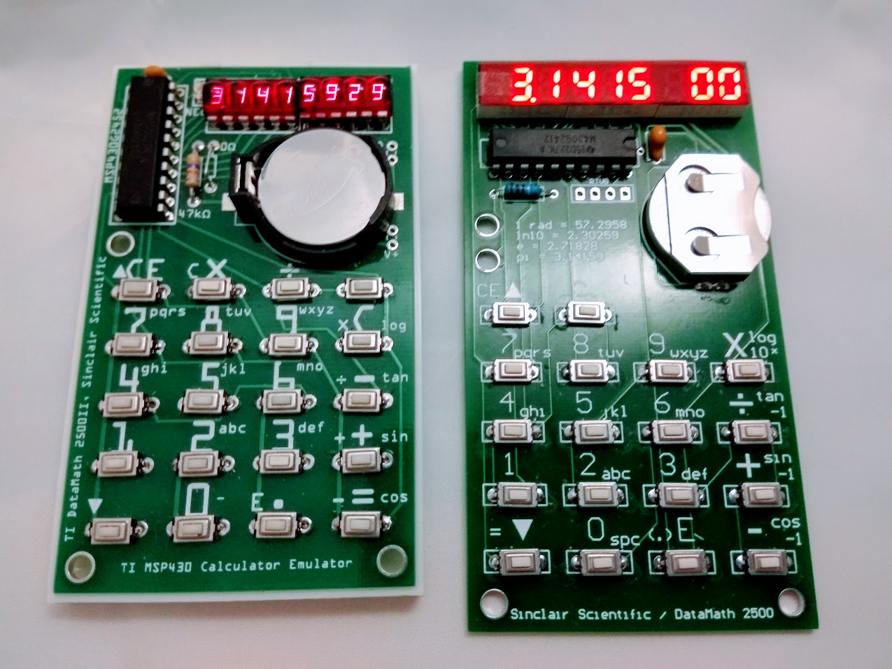
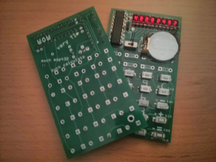
The 2 x HP QDSP-6064 4 digits LED modules (+ 1 lone led) has been replaced by 3 x 2.5” 3 digits modules. Below photo shows the original emulator (left) and the new emulator (right).
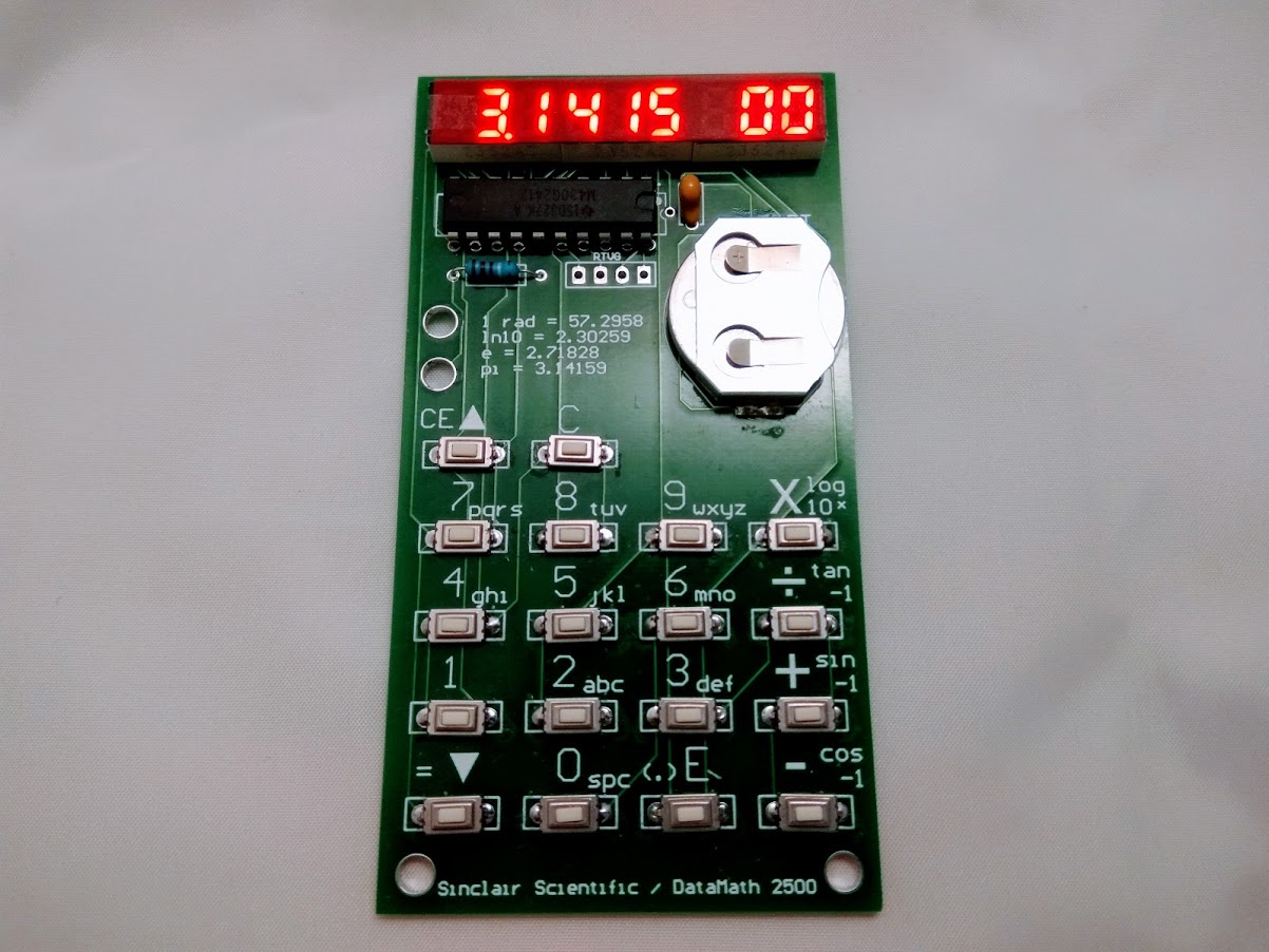
A SMT coin cell holder replaces the original battery holder and now the unit is thinner.
Overall PCB is longer for better grip.
Instead of driving 8 digits of 8 segments (7 segments + dot), the new PCB requires the firmware to drive 9 digits of 8 segments. And we only have 16 IO pins. To overcome this I introduce shared pin for both the 1st digit and the decimal point segment. I.e. this means that there cannot be a show of decimal point for the 1st digit (that led segment cannot be source and sink by the same pin at the same time). This is OK as the 1st digit is basically used to display negative values as a dash.
Schematic and Build Hints (2019 version)
               MSP430G2452
             -----------------
         /|\|                 |
          | |                 |
          --|RST              |
            |                 |       3 x 3 digit bubble led
            |     digit 0 P1.7|----- +-------+ +-------+ +-------+
            |     digit 1 P2.0|----- | % % % | | % % % | | % % % |
            |     digit 2 P2.1|----- +-------+ +-------+ +-------+
            |     digit 3 P2.2|--/-
            |     digit 4 P2.3|--/-
            |     digit 5 P2.4|--/-
            |     digit 6 P2.5|--/-
            |     digit 7 P2.6|--/-        segment a to g + dot........
            |                 |       /                                 ....\
            |                 |      /                                       \
            |   segment A P1.0|-----+-----+-----+-----+-----+-----+-----+-----+
            |                 | _=_ | _=_ | _=_ | _=_ | _=_ | _=_ | _=_ | _=_ |
            |   segment B P1.1|-o o-+-o o-+-o o-+-o o-+-o o-+-o o-+-o o-+-o o-+
            |                 | _=_ | _=_ | _=_ | _=_ | _=_ | _=_ | _=_ |
            |   segment c P1.2|-o o-+-o o-+-o o-+-o o-+-o o-+-o o-+-o o-+
            |                 | _=_ | _=_ | _=_ | _=_ | _=_ | _=_ |
            |   segment D P1.3|-o o-+-o o-+-o o-+-o o-+-o o-+-o o-+
            |                 | _=_ | _=_ | _=_ | _=_ | _=_ |
            |   segment E P1.4|-o o-+-o o-+-o o-+-o o-+-o o-+
            |                 | _=_ | _=_ | _=_ | _=_ |
            |   segment F P1.5|-o o-+-o o-+-o o-+-o o-+
            |                 | _=_ | _=_ | _=_ |
            |   segment G P1.6|-o o-+-o o-+-o o-+
            |                 | _=_ |
            |   segment H P1.7|-o o-+		(not all buttons populated)
            |                 |
             -----------------

Description (original version)
I got introduced to a web based calculator emulation via this thread in 43oh.com forum.
I got interested and start playing w/ the idea of implementing the emulation on an msp430, my code is based on Mr Ken Shirriff’s work from the following pages.
There is also a feature in HaD regarding Ken Shirriff’s Sinclair Scientific work here.
Calculator Functions and Features
As this project emulates the original TI DataMath and Sinclair Scientific calculators, it operates exactly the same as the original ones. The keyboard layouts are similar in both calculators. On the PCB, the dominant key legends (on top of each key) are for TI DataMath, while the smaller legends (top and slightly left of each key) are for Sinclair Scientific emulating.
I had select the MCU clock speed to be 8 Mhz, which appears to more or less matches the speed of the original calculators. I only observe the speed of the original calculators on youtube videos.
The emulating calculator starts / defaults as TI DataMath. If you want to start the calculator as a Sinclair Scientific, hold down key “7” while turning on power.
Holding down “4” while turning on power will place the emulator in a “slow CPU” mode, and it runs 8 times slower than usual as a TI DataMath. This will show how the display (as a register) changes during calculation cycles.
Holding down “CE” while turning on power will briefly show a pre-entered message (8 letters). I added this feature to include personal message as I build these calculators as gifts. To enter a personal message, one can hold down “X” while turning on power. Pressing the keys 0, 1, 2 to 9 allows to select numerics and letters like a old cellphone keyboard, advance letter positions by pressing “+” key. The personal message will be saved in flash memory after the 8th letter has been entered.
- note that the above key sequence is for Version 2 boards only. Version 1 boards uses different keys.
Initial Attempt (Fail) and Version 1 PCB Build (Success)
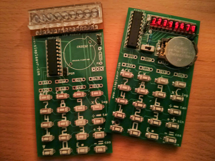
Eventually I built the emulator on a standalone PCB design fitted w/ bubble leds from the ‘70 when the original calculators were made.
This is the original failed build (w/ faulty 9 digit leds) and the 1st successful build on V1 PCB. Next to it is are the 1st two V1 PCB I built. They were given away a few weeks ago.
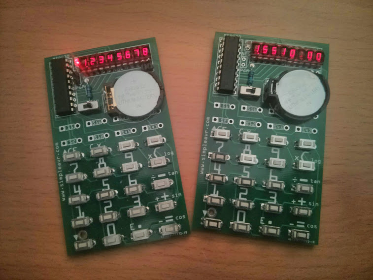
Here is a photo with a blank PCB backside. Eventually I build 3 of these and they are all gone.
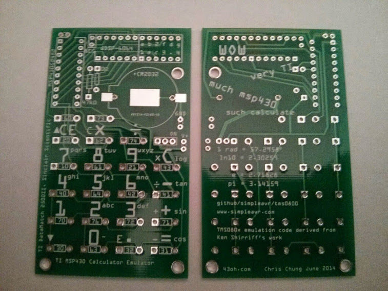
Revised Version 2 PCB Build
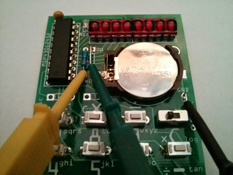
I did a revised PCB to layout the buttons for better ergonomics, also adding a bypass cap and programming “loops” for in-circuit programming. I had proof-build one (from resurrected parts) and am waiting parts for a few more. There is another thread in the 43oh.com forum for a good build / buy.
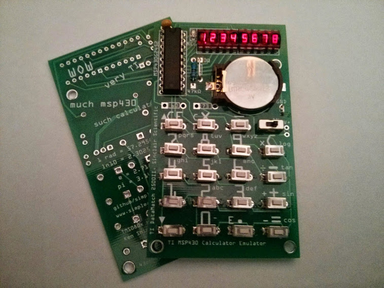
Here is a close-up and a hookup for in-circuit programming (via a G2 LaunchPad)
Parts / Bill of Material
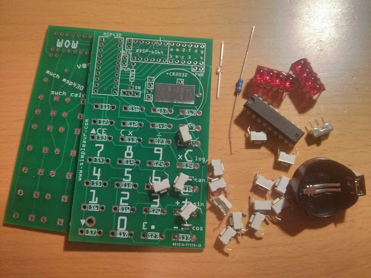
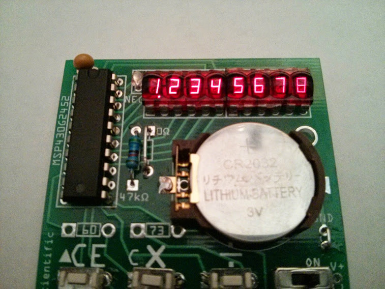
- 1 MSP430G2452, from your the Launchpad G2 (the “other” chip in the package), G2402, G2412 or G2432 will also work.
- 2 bubble led, from sparkfun ($2.95 ea)
- 20 tactile buttons, 6 x 3 x 4.3mm, from DX ($4.76/100)
- 1 spdt dip size switch, from DX ($7.37/100)
- 1 CR2032 cell holder, from DX ($3.14/20)
- 1 miniature 1.8mm red led thru-hole, forgot where I got it (see picture)
- 1 47k pull-up resistor
- 1 0.1uF by-pass capacitor
The miniature red led is to show the “negative” sign. The original calculators have 9 digit displays, since we have only 8 digit, I used a led to show the negative sign when needed.
You can try different CR2032 cell holders, or even paper-clip diys, the pcb make provisions to mount different cell holders.
Schematic, Source Code and Build Hints
It is easier to understand the connections w/ the ascii art schematic, in my opinion
               MSP430G2452
             -----------------
         /|\|                 |
          | |                 |
          --|RST              |
            |                 |       2 x 4 digit bubble led
            |     digit 0 P2.0|----- +---------+ +---------+
            |     digit 1 P2.6|----- | % % % % | | % % % % |
            |     digit 2 P2.1|----- +---------+ +---------+
            |     digit 3 P2.2|--/
            |     digit 4 P2.3|--/
            |     digit 5 P2.7|--/
            |     digit 6 P2.4|--/
            |     digit 7 P2.5|--/         segment a to g + dot........
            |                 |       /                                 ....\
            |                 |      /                                       \
            |   segment A P1.2|-----+-----+-----+-----+-----+-----+-----+-----+
            |                 | _=_ | _=_ | _=_ | _=_ | _=_ | _=_ | _=_ | _=_ | minus led
            |   segment B P1.3|-o o-+-o o-+-o o-+-o o-+-o o-+-o o-+-o o-+-o o-+-(>|)-+
            |                 | _=_ | _=_ | _=_ | _=_ | _=_ | _=_ | _=_ |            |
            |   segment c P1.7|-o o-+-o o-+-o o-+-o o-+-o o-+-o o-+-o o-+------------|
            |                 | _=_ | _=_ | _=_ | _=_ | _=_ | _=_ |
            |   segment D P1.1|-o o-+-o o-+-o o-+-o o-+-o o-+-o o-+
            |                 | _=_ | _=_ | _=_ | _=_ | _=_ |
            |   segment E P1.5|-o o-+-o o-+-o o-+-o o-+-o o-+
            |                 | _=_ | _=_ | _=_ | _=_ |
            |   segment F P1.4|-o o-+-o o-+-o o-+-o o-+
            |                 | _=_ | _=_ | _=_ |
            |   segment G P1.0|-o o-+-o o-+-o o-+
            |                 | _=_ |
            |   segment H P1.6|-o o-+       (not all buttons populated)
            |                 |
             -----------------
The source code is in github
There is also good amount of H/W information commented inside the code
If you plan to design your own PCB, the basic principle in relationship w/ the code is
- P1 for LED segments
- P2 for LED digits
- P1 also for key button scanning
- You can move things around as long as you observe the above. I.e. If it fits better on your PCB, you could swap digit 1 w/ digit 3, segment A w/ segment E, etc, etc. All you need is to change #define in a header file and compile.
There is a build thread in 43oh.com. If you have questions I can answer them over there.