rtc-clock
RTC Clock
A minimalist digital clock with crystal time keeping.
[Nov 2010] Initial write-up
[May 17, 2013] Adjust source code for newer mspgcc. now source in github, link at bottom
[May 20, 2013] Add setup instruction video
Description
This is a enhanced version of the 3p4w clock project. Having finished the 3p4w clock, the 3p4w clock project started out as a excercise to do “something” with the new ti value series MCUs. In practice the 3p4w clock was not accurate for normal day to day use. With these enhancements i made an attempt to make it usable to keep it on my bedside table. i.e. Waking me up and not late for work.
basically i am adding a cheap rtc timing keeping chip to the original design. I do not consider this an elegant solution as it requires additional parts. My origianl goal on the 3p4w clock project was to build a working led clock w/ minimal components. With the limited io pins on the 14 pin msp430g2211/2231 devices, it is just not possible to do that. Accurate time can only be kept with the use of external crystal, but this will take away precious io pins that is neccessary to drive the 4 x 7 segment led display. May be when ti starts shipping 20 pin value line dip devices i can make use of it to make a better clock.
Having said that, adding the rtc chip do have some benefits. The project still stays on one single mini breadboard. I can now have date and day of week function. The clock can now go into lpm4 deep sleep for further power saving.
There is no special design features here, the led driving mechanism (and how i drive the led module w/ minimal pin counts) are described in the 3p4w clock page. Worth mentioning is that i am using i2c to talk to the rtc chip. I have to use software i2c over the msp430 builtin. All the available io pins are connected to the led module and the particular 2 pins need to do hardware i2c (P1.6, P1.7) is connected as cathode + anode for the led display. I had to pick 2 io pins that do not interfere w/ each other. i.e. They must be both anode or both cathode on the led display. That’s the reason i have to use software i2c.
The mcu fetches time information from the rtc chip at the zero second of every minute and sychronize it’s registers. I have to initailize the corresponding port io pins whenever this happens, as the io pins are shared between led multiplexing and i2c (and button press, and pin interrupt,…)
When the mcu goes into non-displaying power saving mode, the mcu switches the button pin from input (polling) to pin interrupt, commands the rtc (via i2c) to generate hardware interrupt upon alarm event, and goes into lpm4 deep sleep. In lpm4, all clocks in the mcu are turned off and the project only wakes up when receving a button press interrupt or a alarm interrupt from the rtc.
i measured 2-6mA current when the clock is active (depending on the led dimmer/brightness level) and when sleep it’s 70ua, i don’t know how it uses so much, from the datasheets of both mcu and rtc chip i should be getting 2-3ua when sleep. i guess i am not setting up the mcu ports properly before going to sleep. anyway it is not bothering me and i leave it as it. 2 x AAA batteries will typically give you 1200 mAH, so i figure if i had the clock active 8 hours a day, i will need to replace the batteries like every month, more or less. of course if u do not turn it on during all day it will run much longer. and you always has the option to supply power via a power adapter.
i had also taken out the temperature display function due to code space. i could make an effort to have it included but it’s something i don’t need. this way i can also use the msp430g2211 chip and save the 2231 for other projects. the project rings in at around 1950 bytes when build with mspgcc, may be iar can do better.
Features
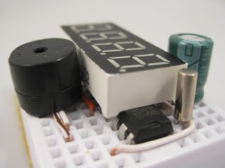
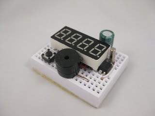
- 8 parts on a mini breadboard
- battery operated from 3V
- use of rtc chip and 32Khz crystal for time keeping
- as accurate as any crystal driven clock
- lpm4 deep sleep mode when not displaying
- display of hour/min, seconds, date/day of week
- one alarm
- alarm triggered by rtc chip during clock sleep
- capacitor used as power failure (when you change batteries) backup, this give you a couple of hours, optionally supercap or 1.5v button cell can be used if you need more backup time
Parts List
- MSP430G2211 (from your Launchpad kit)
- 4 digit 7 segment LED display (red works best on 3V power)
- tactile button
- buzzer 3V
- rtc chip NXP PCF8563
- 32Khz watch crystal
- small signal diode (preferrably schottky)
- eletrolytic capacitor 470uH (other values are fine, i pick this because i got this in turquoise color than the usual royal blue)
- optionally u can bridge a variable (or fixed) capacitor between crytal (OSCI, oscillator input, pin 1) to get better accuracy, i don’t see the need
the LED display is commonly available in ebay, look for those 0.4” or 0.36” 4 digit displays, you will want to make sure it’s common cathode and the pin layout matches (most do)
the rtc chip can also be sourced from ebay, i choose the pcf8563 over the more popular ds130x only because they are cheaper and readily from ebay, the basics are the same, you can easily change the code to talk to some other devices
        ___a__
      |      |        (0) A  F (1)(2) B
     f|      | b      -+--+--+--+--+--+
       ___g__        |                 |
     e|      | c     |Pin1             |
      |      |        -+--+--+--+--+--+
       ___d__          E  D  .  C  G (3)
Application Notes
- single button press toggles thru hours + minutes, seconds, date + day of week, alarm time and sleep modes
- long press enters setup mode, subsequent long press rotates thru menu
- unlike 3p4w, long press enter setup for the current mode. i.e. long press when displaying hour + minute will allow you setup the current time. likewise if you want to setup the alarm, you should first short press to change mode for alarm display, and then long press to enter and setup the alarm.
- choice of 12H or 24H display
- long press when displaying seconds allows for cycling possible led dimming values (4 levels)
- led segment multiplexing includes time delays to compensate for brightness differences for individual digits. ie. when dislaying a digit ‘8’ we stay longer than displaying a digit ‘1’ to compensate for the loss of brightness when driving multiple segments.
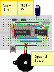
Breadboard Layout
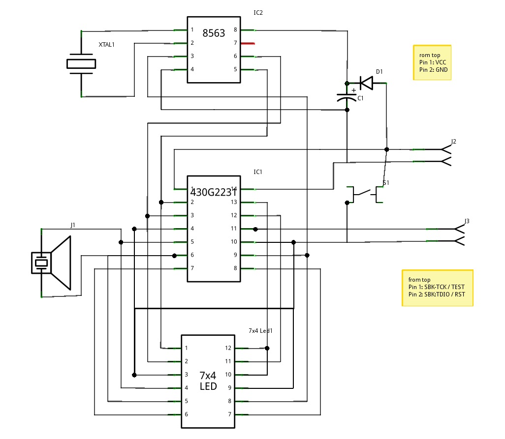
Schematic
Source Code
s(click to download rtc-clock.c)
s(click to download i2c.h)
latest code now on my github repository
Troubleshooting
- check connections, there’s not that many
- if using a different rtc chip, u may need to tweak i2c timing (see i2c.h)
- crystal should have a 15-22pf capacitor bridging ground, see if it helps if u are in trouble