old_projects
RFM12b Spectrum analyzer
[November, 2010] Initial write-up.
[Nov 10th, 2010] this project has been entered in the 43oh.com november (2010) project of the month contest. more info here
RF Spectrum Analyzer Based on the TI Launchpad and the RFM12b RF Module.
Description
This is a simple rf spectrum analyzer project based on TI Launchpad. I have been working on other rf transceiver projects and in need of a simple rf spectrum analyzer to help me visualize what’s happening.
This is a linux project, I had given attention with my best knowledge to make provisions so that it can be built under windows. However I do not have the time and resources to try out everything under windows.
I did successfully built and run the project under windows 7 w/ TI CCS IDE, for host visualization script, it also works under windows but required you to install some unixish packages (cygwin and more)
I need something simple to show the pattern of frequency hopping. I do not need very accurate display of rf power. The Launchpad came in handy as it is inexpensive and contains fast ADC functions. The included usb to uart is a plus as i can communicate data between the MCU application w/ a PC side application for visualization. There are around a dozen or so commands that you can issue via SPI to control the RFM12B, as well as sending and receiving data.
A RFM12B module is used to capture signal strengths of different frequencies. The RFM12B utilizes a SPI interface to communicate to a MCU. A software SPI is implemented in this project for simplicity.
Initially I set out to use the documented DRRSI function. But the result is poor, to do this you have to set a “threshold” signal level (between 0-5) via a SPI command, and read from the RFM12B whether the signal strength is met. Apart from the very poor resolution (only 6 steps), you need to do perform this for each threshold steps, meaning 6 times for each frequency. The settlement time is also not acceptable, in that (from the data-sheet) you need to wait for 500us to get proper results.
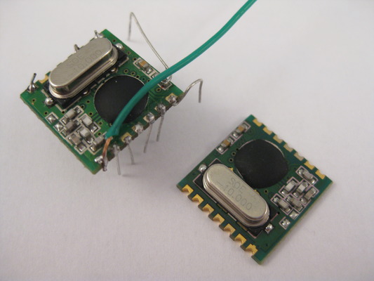
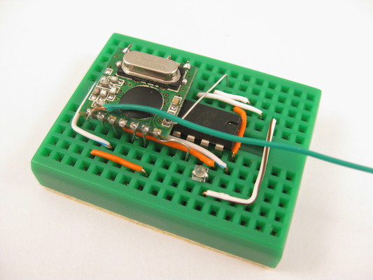
I discovered that are mentions of a ARRSI signal that you can use to take analog signal strengths, it is only available on the SMD type of modules and it is not on any of the pin-outs, you will need solder an extra pin out from the module. You can see the extra add-on lead running from the surface of the pcb module, this is where the ARRSI lies.
After some trial and error I was able to get rather reliable readings from this ARRSI pin. The range of the ARRSI output is between 0.7V and 2.2V, which match what i discovered via google. The timing is important to a fast and successful ARRSI read, if we are to perform the ADC immediately after issuing a “read” command (0xb000), I can get decent readings.
The Launchpad firmware basically received commands from the PC side perl script to start sampling for signal strengths, the frequency and signal strength are then sent to a host application (written in perl) for visualization. There is a threshold in the firmware that prohibits data sending if the signal strength is below it. This is needed as the LaunchPad can only do 9600bps communicating w/ the PC and if we include all the zeros and noises for sending, the uart is not able to catch-up.
The current firmware also does not read all possible frequency due to the uart bottleneck, instead of reading at 7.5Khz gaps the firmware is only reading 16 x 7.5Khz (120Khz) steps. The valid range for the RFM12B is between 36 and 3903 (3867 steps) and we are doing 241 steps per sweep. The Launchpad would perform a full sweep of 241 frequency steps, reporting those frequencies and signal strengths if they are above a threshold, and at the end of a full sweep, send a signal as indication.
On the PC side, the perl script will send a “start” command during start-up. It then reads data from the Launchpad, continuously updating the display grid to show “near” real-time results. There are some other settings on the perl script that affects the visualization and is described separately.
Although the RFM12B module I used is tuned for 915Mhz, I am able to get signal strengths (may not be optimized) from the 433Mhz and 868Mhz bands.
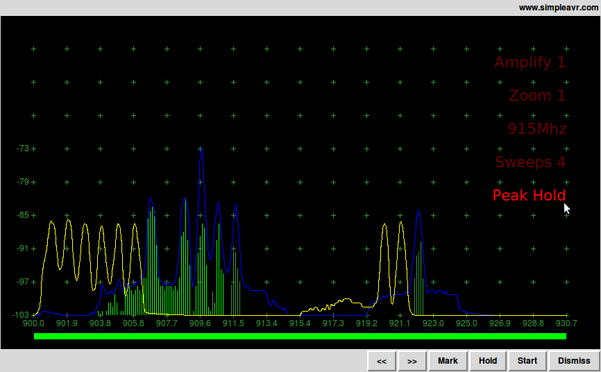
Host Side Application written in Perl
Show here is the perl script i used for visualization. I am using perl/tk and device::serial packages. The green bars are the current signal strength of various frequencies. The blue peaks are peak hold values. The yellow curve is a previous peak hold curve that I had “marked” for comparison.
The test scenario shown was on a FHSS transceiver pair working together. At an initial partnering stage one transceiver set out to look for a partner (show in the yellow curve), once partnering is accomplished, they switch to another hopping list to perform data exchange (blue curve and green bars).
Features
- Higher resolution w/ analog ARSSI reads
- Adequate speed to show FHSS activities
- “915Mhz” RFM12B module used, can also set at 433Mhz, 868Mhz with less optimal results
- “Amplify” setting (software) to visualize weak signals
- “Sweep” setting to accumulate and average over time, used to analyze intermittent signals (digital, RHSS, etc)
- “Zoom” to zoom in part of the capturing spectrum
- “Peak” and peak hold function in gui for better visual and signal comparison
Parts List
- TI Launchpad kit
- Led (optional, for command received indication)
- HopeRF RFM12B SMB module (433Mhz, 868Mhz or 915Mhz band)
It is important to get the RFM12B module in SMD format, as the ARRSI is not available in the DIP format.
Notice in the above picture that a lead is added to the ARRSI spot, you have to be careful and if possible, use a fine solder tip (i didn’t have one). Pre-tin your lead properly and limit your solder time.
Application Notes
- Plug-in Launchpad, start perl script on PC side
- Signal streaming should start immediately, if you got not signal, there will be nothing showing on your screen
- Click ‘hold’ and ‘start’ to stop and start signal streaming from Launchpad
- Click ‘915Mhz’ to toggle between different frequency bands (i.e. 433Mhz, 868Mhz, 915Mhz)
- Click ‘sweeps’ to set the number of sweeps to accumulate for averaging, a low number will allow fast showing of data and a high number will tell the perl script to accumulate and average over several sweeps. this allows for visualization of digital (i.e. intermittent) or FHSS signals
- Click ‘amplify’ to amplify the signal strength. this is purely visual as we just multiply the signal strength for easy viewing
- Clock ‘zoom’ to zoom into a part of the spectrum, not really meaningful at this stage as the firmware is not capable of bands narrower than 90Khz
[Nov 7th, 2010]added ‘sampling’ options to change frequency gaps, i.e. default is sample every 120Khz on the 915Mhz band, now can be down to 7.5Khz.
Credits and References
HopeRF, RFM12B manufacturor and resources hereTI LaunchPad wiki hereblog.strobitics.com had a tutorial series on the RFM12B herejeelabs had a host of topics and forum posts on the RFM12B, start hereFor software uart, i learn and use code snippets from ti’s example, also njc’s uart tutorial and hodgepig’s LaunchPad StakulatorMost references ceased to exist, please google for information instead
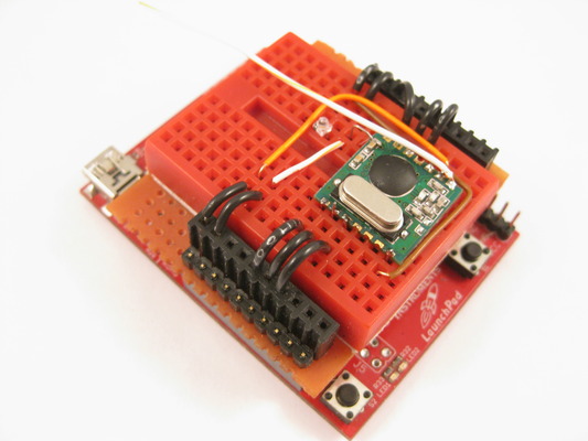
Project Layout
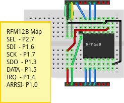
The two female header rails represents the LaunchPad J1 and J2 headers, please correspond to the photo.
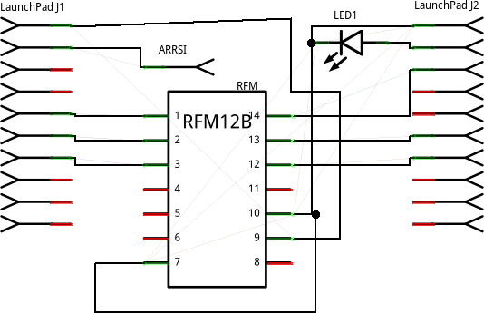
Schematic
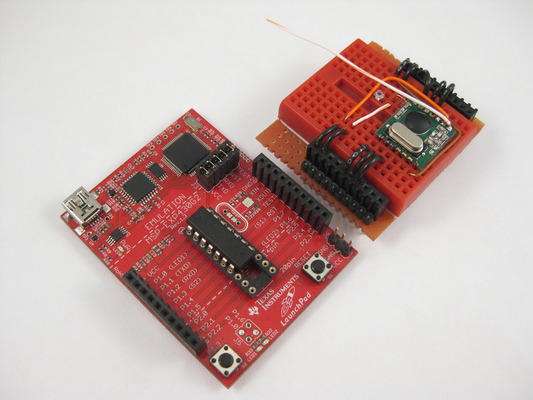
Alternate Construction
You can, if you wish, free up your launchpad and make this project as a standalone breadboard project. Place the MSP430G2231 chip underneath your RFM12B module and run your jumper wires. They all fit rather nicely.
For uart communications you can use a FTDI cable, or, as in my case, hack a nokia ca-42 cable as shown here. I can no longer find those cables that have a Vcc supply wire any more. Looks like every supplier is making only 3 wires available (gnd, rx and tx). I had to cut out the assembly and have the pcb exposed, then run a 3.3v (along w/ gnd, rx and tx) through a 4 wire header jumper. This way I do not need extra power for the finished setup.
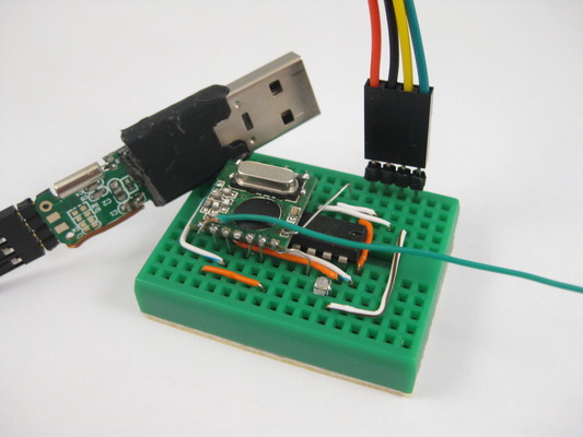
Another benefit on using a usb to serial cable is you can run your uart at far higher speed (57600bps i did), with the launchpad 9600bps is the limit.
Project Status
The spectrum analyzer had met my initial objective as a tool to diagnosis my other RHSS projects. It is fast enough to show digital signal patterns and fairly accurate to give me some idea of signal strengths. However there are improvement that can be made.
- Speedy uart. This should solve part of the last problem if implemented. The current bottleneck on the device is related to the fact that I am only doing 9600bps uart w/ the PC. In the alternate (launchpad free) construction I am using a nokia ca-42 cable and getting better performances.
- Crc and other means to validate incoming data, as we are using internal oscillator and software uart here, there is always chance that false reads being made.
- ADC conversions is fast but can be faster by implementing continous reads.
- Accurate signal strength reading. Currently i am just showing ADC results from RFM12B ARRSI reads, I had no clue on the real mW or dbm values, I am no RF expert.
Source Code and Firmware Building
Following are instructions for linux only, my environment is ubuntu 10.04, other distros should work as long as you had installed the msp403 toolchain and mspdebug properly.
Source file are in dos format as linux is more tolerant and will compile w/o problem. Anyway if you need to switch formats you can open them w/ vim and do “set ff=dos” or “set ff=unix”
You can create a directory and place the following files in them
Click to download rfm12.h
Click to download ezrfm.c
Source code now in my github repository
I do not have a makefile for this to compile, I use a bash script to compile most of my projects, it is mentioned on my launchpad shield page, scroll down to the section “workspace directory layout” and get the details.
Or you can do the following
  msp430-gcc -Os -mmcu=msp430x2013 -o ezrfm.elf ezrfm.c
  msp430-objdump -DS ezrfm.elf > ezrfm.lst
  msp430-objdump -h ezrfm.elf
  msp430-size ezrfm.elf
To flash firmware, attach your launchpad and do
mspdebug rf2500 "prog ezrfm.elf"
Windows Build via TI CCS
- Create a new project ezrfm and copy rfm12.h and ezrfm.c into your project directory
- Select gcc compatible option in your project properties
- Rebuild project
Host side visualization script
This is the perl script that runs on the PC side
Apart from core perl, you need to install (via cpan)
- Tk
- Device::SerialPort
- Time::HiRes
Click to download ezrfm.pl
Source code now in my github repository
Window users, you have to install a brunch of things for this to work
Cygwin, during which need to include
- perl, tk, make, gcc
- X11, xorgserver, xinit
- After cygwin installed, use cpan to install these perl modules
- Tk, Device::SerialPort, Time::HiRes
- For Device::SerialPort, the test will fail, need to use -f (force) option
- You have to start X11 server before running the script. i.e. startxwin
- com port conventions are different. COM1 is /dev/ttyS0 in cygwin, adjust perl script accordingly
Troubleshooting
- Adding the ARRSI can be a challenge, tin the lead you are adding and limit your solder time. Apply flux before soldering and use a fine tip if you can. You won’t know how easy one can tap the solder tip on the tiny pad and have the whole smd resistor lifted.
- There are no factory calibrated values for the MSP430G2231 on 8Mhz DCO, you need to try different values or use a calibration firmware and crystal (from ti examples).
- Don’t assume software uart is reliable, you may miss or gain some higher bits (especially 0x40-0xa0 range) if your timing is not right. You may not even notice them. I used a seperate script to test the reliably of the comms during development, basically a stress test on different baud rates w/ full range of data.
Notes
Will expand webpage from feedbacks, especially on window builds as i am not too confident on the current instructions.
Will include more information on the RFM12B module when time permits.
This project is very outdated and is not neccessary a good solution in 2018