old_projects
Multimode Clock
[November, 2010] Initial write-up.
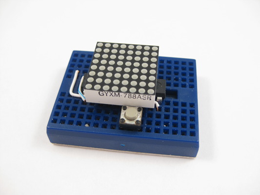
Breadboard based clock Project with atttiny2313 Microcontroller.
Description
This is a mutli-mode clock project based on attiny2313. It employs a 8x8 led matrix as display. With the limited resolution, This 12 hour clock shows time in 6 different modes.
HHMM mode, typical hours plus minutes scrolling digits with colon separator.
Seconds mode, shows only seconds.
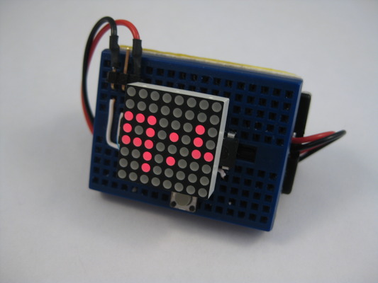
Tix mode (below), led matrix is divided into quadrant, the upper quadrants shows the hour in bcd (binary coded decimal) values. They are represented by the number of dots to indicate the digits. The lower quadrants show the minute in bcd. i.e. for 12:37 it shows no dot + 9 dots on the upper half and 3 dots + 7 dots on the lower half.
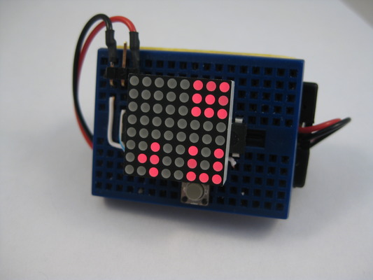
Dice mode (below), the led matrix is divided into two set of ‘dices’. with the upper pair showing hour from 1 - 12, the lower pair of dice shows minutes in 5 minute increments. i.e. for 9:45 it shows dice value upper 9 + lower 9 (9 hour, 9 x 5 min).
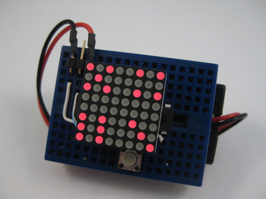
Binary / BCD mode, (below) the hour, minute and second digits are show as binary dot on different rows in the led matrix. the rows 0 and 1 (from top) represents the hour digits, rows 2 is blanked, row 3 and 4 represent the minute digits, row 5 is blanked, row 6 and 7 represents the second digits.
The circuit employs row and column multiplexing to drive the leds, one row at a time, this gives a 12.5% duty cycle when “sets” of leds (8 of them in each of the 8 rows) are turn on briefly. Current limiting resistors are eliminated to save breadboard estate and as we are not constantly driving individual leds, they are not going to be damaged.
The control (user interface) is also arranged so that we only use one tactile button for input. The firmware capture long button presses (press and hold) for menu rotation and normal button presses for menu selection.
This is a hobby project and the clock is only as accurate as your internal oscillator calibration. I had not use a crystal in this project as doing so will upset the “matrix on top of mcu” breadboard layout. a crystal can be used to increase accuracy on a alternate breadboard layout (or pcb). with software compensation, i can achieve may be within 2 minutes off a day. I would need to adjust the time every 3 or 4 days to keep it usable. This is more a cubicle talk piece than a swiss time piece.
Features
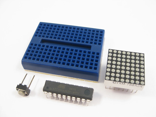
- Minimal components, 3 parts
- Battery operated from 3V to 5V
- Use of watchdog timer to keep time, power-down sleep mode takes about 1uA power
- Calibration allow setup of seconds to gain for each hour
- This is a 12H clock, not 24H and has no AM/PM indicator
- Not very accurate, planning to add RTC chip
Project fuse setting
- Setting at 1Mhz to conserve power
- Change according to your programmer and port
avrdude -c usbtiny -p t2313 -P /dev/ttyUSB0 -V -U lfuse:w:0x64:m -U hfuse:w:0xdf:m -U efuse:w:0xff:m
Parts list
- attiny2313v (v is low power version that works with 3V)
- 8x8 LED matrix display (red works best on 3V power)
- Tactile button
Application notes
- Short key press in display mode cycles through HHMM, seconds, tix, dice, binary and sleep modes
- Long press enters setup mode, subsequent long press rotates thru menu
- Menu items cycles thru SE, AJ, DM
- In ‘SE’ time setup mode, short press enters setup
- Once in setup, short press increments digit values (hours, minutes) and long press confirms
- In ‘AJ’ calibration setup mode, minutes and seconds can be entered. this represents the time to ‘gain’ for each hour
- When in sleep mode, MCU goes in power down mode, consuming less than 1uA of power, watchdog timer is set so that system wakes-up every 1/8 second. this, however makes the time keeping to be always slow as it takes a few cycles to power up the MCU again. therefore we must have a calibration value to keep accurately
- Last setup values saved in EEPROM and will be used for the next power up
- In ‘DM’ dimmer setting, short presses cycles through available brightness levels, long press confirms setting
- Led segment multiplexing includes time delays to compensate for brightness differences for individual rows.
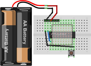
Breadboard Layout
The 8x8 led matrix has dot size of 1.9mm and is of common cathode, if you have common anode type, you can change a few lines in the code for adoption. See the following diagram and see if you have the right pin-outs. It appears they are quite common and if you purchase via ebay most suppliers have the same pin-out even if the model number is different.
           Gd Rt V+ Ck MI MO (tinyusb programmer)
            +  +  +  +  +  +
   +=====================================================+
   |  .  .  .  .  o  .  .  .  .  .  .  .  .  .  .  .  .  |
   |  .  .  .  .  .  .  .  .  .  .  .  .  .  .  .  .  .  |
   |  .  .  .  .  .  +--+--+--+--+--+--+--+  .  .  .  .  |
   |  .  .  .  .  . C8 C7 R2 C1 R4 C6 C4 R1  .  .  .  .  |
   |  .  .  o  o  +--+--+--+--+--+--+--+--+--+  .  .  .  |
   |        |  | |+ b7..6..5..4..3..2..1..0 d6|          |
   |        |  | |R d0..1 a1..0 d2..3..4..5  -|          |
   |  .  .  |  |  +--+--+--+--+--+--+--+--+--+- .  .  .  |
   |  .  .  |  +--o  +--+--+--+--+--+--+--+  .  .  .  .  |
   |  .  .  |  .  . R5 R7 C2 C3 R8 C5 R6 R3  .  .  .  .  |
   |  .  .  |  .  .  .  .  .  .  .  .  .  .  .  .  .  .  |
   |  .  .  |  .  .  .  .  .  .  o..B..o  .  .  .  .  .  |
   |  .  .  +--------------------------------o  .  .  .  |
   +=====================================================+
                                            Gnd
Schematic
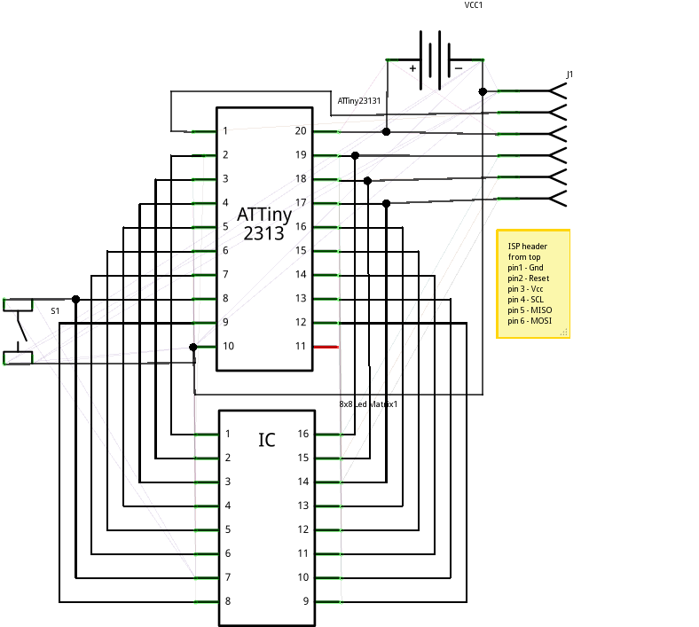
Observe the ISP (in-system-programmer) pin-outs, this is a non-standard pin-out but works very well on breadboards, they lin up nicely on one side of the attiny2313 and just need to connect RESET + Gnd to complete the circuit. i am using a “usbtiny” type of programmer to do the flash.
Assembling
- Follow breadboard layout and place two jumper wires on mini breadboard
- Insert attiny2313v
- Insert tactile button
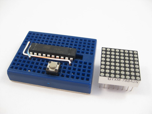
- Finally insert 8x8 led matrix on top of attiny2313v
Source Code
click to download mclock.c
click to download makefile
[April 26th, 2011] Replace makefile, the old one does not make hex output, just elf, now it makes both.
[December 23rd, 2010] Source code updated and will build on avr-gcc 4.3.4 within 2k limit. will work on using crystal for accurate timing.
[December 14th, 2010] Someone tried to build and w/ avr-gcc 4.3.3+ the hex is too big. i used to build this w/ 4.3.2 and get a very tight 2046 byte hex. i am attaching the hex file here. will find time to work on the source code / makefile switches to make it fit again in gcc 4.3.4. for now you can use the following binaries
click to download mclock.hex
click to download mclock.ee.hex
Source code now reside in my github repository
The source runs at about 500 lines and is rather self explanatory. The project was built in a linux ubuntu lucid box with avr-gcc toolchain.
Although the project uses only a handful of letters for menu selection, i had included 38 characters in the rom. i.e. digits 0-9, letters A-Z, a ‘.’ and a space character.
The tic mode and dice mode pattern selection is not true random as we had code size restriction.
Per row leds brightness are compensated in software by adjusting how long a row of leds stays on and off. i.e. for rows with all 8 column leds on, we stay longer to make them appears to be as bright as those rows that have only one or two leds on.
Watchdog timer is used as this allows for sleep mode to prolong battery life. This means that the clock is not that accurate. During sleep the timer wakes the system up 8 times a second to see if a key is pressed and to advance the clock.
If you have any questions, feel free to comment here, I will try to address them. I know this write-up does not have a lot of detail. I prefer to enrich this page with feed-backs from viewers.
Troubleshooting
- Check connections
- Check fuse setting on attiny2313
- Adjust timing by adding -B xx parameter to avrdude, if you have problem flashing