old_projects
3p4w Clock
[August 2010] Initial write-up.
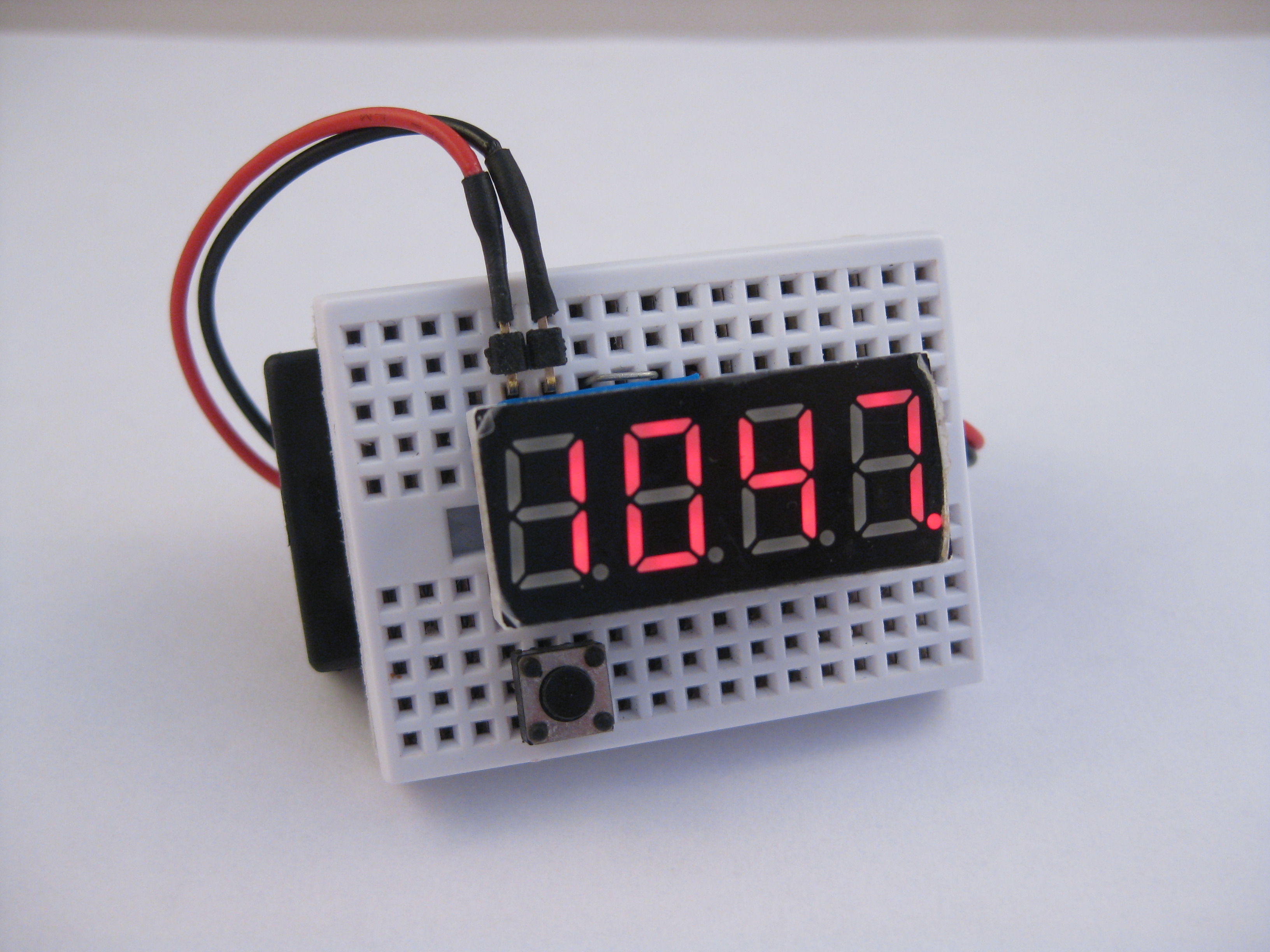
3 Parts 4 Wires Clock. Digital clock with absolute minimal parts.
[Oct 16, 2012] 3p4w-clk20.c uploaded, to support launchpad v1.5 20pin devices.
Featured in www.43oh.com
- Migrate to v1.5 lauchpad, provide B(alternate layout for 20pin devices)
- Comment / uncomment #define DEVICE_20P for 14pin and 20pin devices
- Tried w/ msp430g2452
- Linux build observe changes in mspgcc, i.e. #include
, etc - Now autodect 32khz crystal, if present, B(will provide much more accurate time)
Click to download 3p4w-clk20.c
Click to download 3p4w-clk20.elf
Click to download 3p4w-clk20.txt
Source now reside in l(my github repository:https://github.com/simpleavr/old_projects/3p4w_clock)
[Jul 29, 2011] New version of 3p4w-noegg.c uploaded, includes two line changes (normally commented out) to allow for common anode led modules. If you are using common anode led module (but the same pin-out) search for “anode” in the source code and un-comment them.
Also if u flash this project and found out that the clock is slow, digits are not showing all at once, it is due to the fact that there are garbage values (usually 0xff) in the eeprom. This leads to excessive time taken to multiplex between different digits. U should press button long-long-long to go to the “brightness” menu, then press short-short-short until the display fixes itself.
[Dec 14, 2010] Please see rtc project page, i had added rtc chip to this circuit to get accurate time and also calender function
[Nov10, 2010] Easter egg uncovered by jbremnamt, see this thread in www.43oh.com
jbremnamt is also a breadboard fan and has been featured in hackaday
Clock also behaving badly as the temperature drops and we turn the heater on, working on adding rtc to the design that will provide accurate time and calender, still stays in a mini breadboard, check again in a few weeks.
Description
This is a simple clock project based on ti MSP430G2231. This comes included in the $4.30 TI Launchpad package. The project objective is to create a working clock with minimal components. In order to achieve this objective, current limiting resistors for the LED display were omitted. Also multiplexing is used to reduce the io pins needed to drive the LED display.
For a 4 digit x 7 segment display we need to drive 32 leds (including the decimal dot). The MSP430G2231 has only 10 io pins at most, so instead of driving individual leds we use multiplexing to briefly turn on and off different led segments. We do this ever so quickly to fool our eyes that the leds are constantly on. This is also known as POV (persistence of vision). the control (user interface) is also arranged so that we only use one tactile button for input. The firmware capture long button presses (press and hold) for menu rotation and normal button presses for menu selection.
Features
- Minimal components, 3 parts (4 parts if you need alarm)
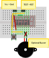
- 4 jumper wires on a mini breadboard
- battery operated from 3V
- Use of internal VLO clock (~12Khz) to keep time, power-down sleep mode takes less than 1uA power
- VLO is calibrated against DCO at start-up, DCO in turn use factory calibrated value
- Manual calibration allow setup to run faster (in about 0.5% increments) to compensate for cycles lost due to power mode switching (i.e. sleep / wake-up cycles)
- Fairly accurate if you consider that there is no crystal used
- Ambient temperature read in metric and imperial units
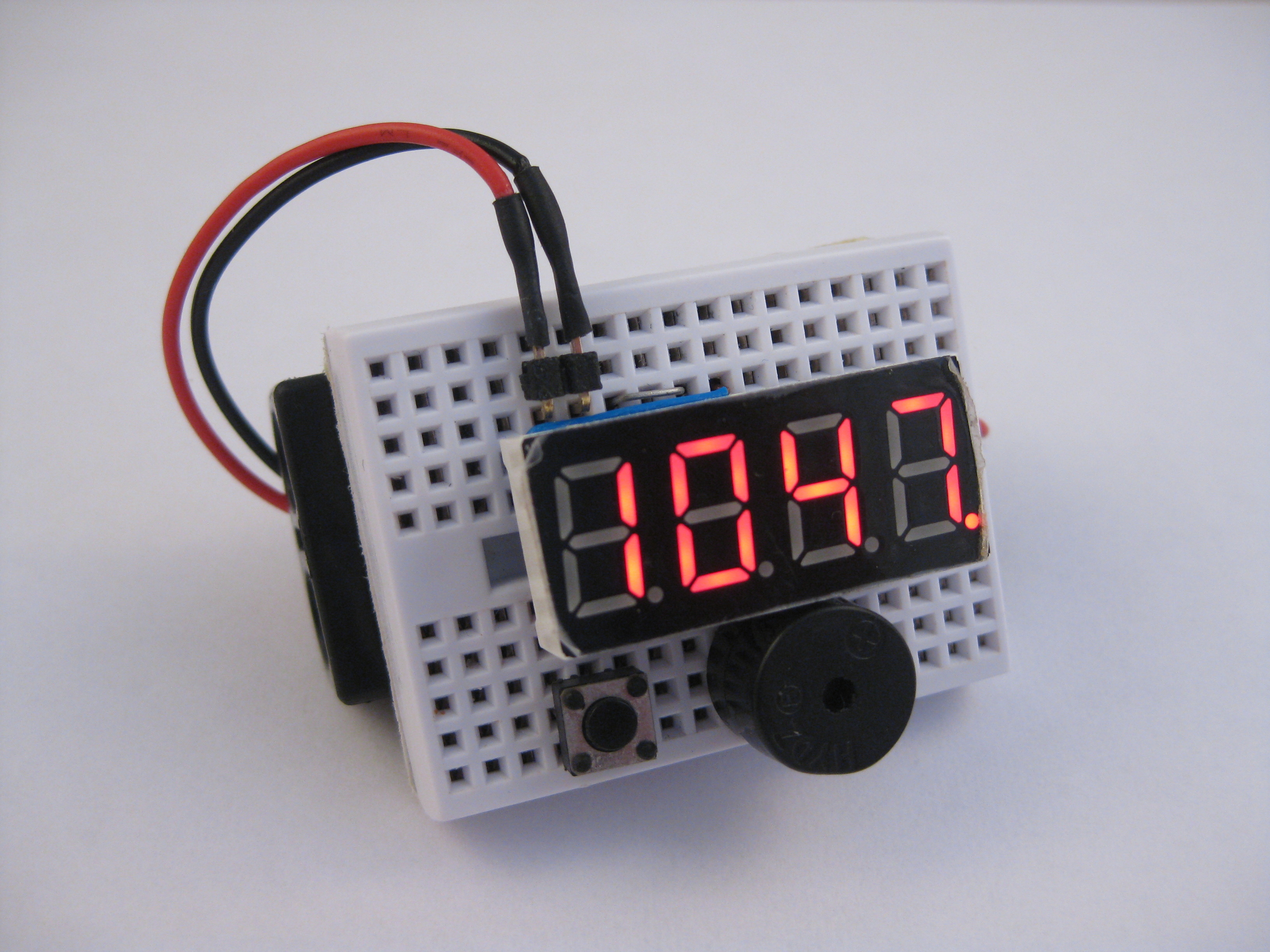
- Optional alarm if you connects a buzzer (auto-detect), this will make the 4p4w clock
- Hidden Easter egg function for you to find, you can build the project and poke around to find it, or you can try disassemble the firmware provided
Special Design Notes
- To have full scan on 8 (7 + dot) segment and 4 digits, typically we need 8 + 4 io pins, with only 10 io pins for this device, two segment / digit pairs shares the same pin this allows us to display more w/ the following sacrifices.
- Digit 0 and segment f are shared with the same pin, this means that we cannot show segment f in in digit 0, which is ok for a clock as showing the numbers 1, 2, 3, 7 does not require segment f and we only need number 1, 2 at digit 0 position for a 12 hr / 24 hr clock.
- Digit 1 and segment ‘decimal’ are also shared, i.e. we cannot have decimal point at digit 1 position (middle of display), this is still ok but means that we cannot have a decimal hour and minute separator as most clocks do.
- The choice of selecting the two ‘shared’ segment / digit has been made to minimize jumper routing while still doing what a clock should do, one important design goal is to have the project stay in a 170 tie-point mini breadboard, and we are moving parts + complex firmware to achieve this wherever possible.
- Although we are not using the SBW pins (IO and Clk), they are inheritically connect as they share the same breadboard column, this usually have no impact except that the SBWDIO pin is also the RESET pin, which must be pull high at all times. with all the LED scan happening we will get resets all the time. the solution here is to enable NMI so that RESET signals are ignored (they triggers a non-mask-able interrupt instead of resetting the MCU). but before we can setup NMI the system still need to be running, in order to provide a logic high on RESET during power up we have to purposefully place our tactile button to this pin. the tactile button thus serves two purpose; it’s normal role for user interface, and upon power up, as a ‘boot’ button to let the initialization firmware kicks in.
One would argue that we can introduce additional charliplexing and run a full 8x4 digit scan w/ just 10 io pins. Yes it is possible to have 2 pins to drive 4 digits but we have to use a pair of 2 digit LED displays w/ opposing anode and cathode layouts, this will generate a lot more external wiring. This is rejected as the primary goal in this project is to build the simplest LED clock possible and have it fit in the smallest breadboard available.
Parts List
- MSP430G2231 (from your Launchpad kit)
- 4 digit 7 segment LED display (red works best on 3V power)
- Tactile button
- Buzzer 3V (Optional, and becomes the 4p4w clock)
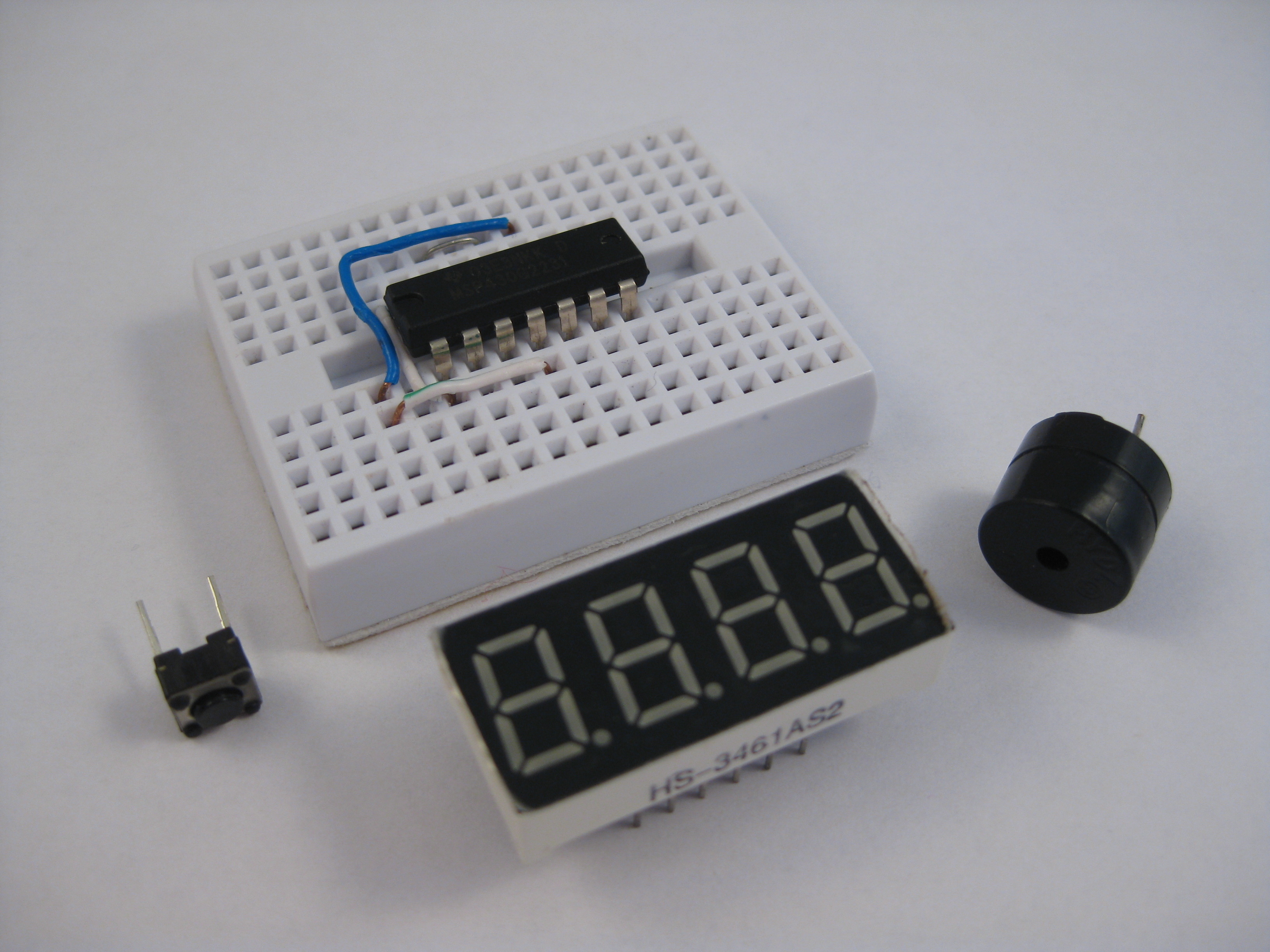
The LED display is commonly available in ebay, look for those 0.4” or 0.36” 4 digit displays, you will want to make sure it’s common cathode and the pin layout matches (most do).
        ___a__
      |      |        (0) A  F (1)(2) B
     f|      | b      -+--+--+--+--+--+
       ___g__        |                 |
     e|      | c     |Pin1             |
      |      |        -+--+--+--+--+--+
       ___d__          E  D  .  C  G (3)
Application Notes
- If buzzer is connected, firmware allows for alarm setting and usage
- Single button press toggles thru hours + minutes, alarm on/off + seconds, and sleep modes
- Long press enters setup mode, subsequent long press rotates thru menu
- Menu items cycles thru SEt, ALr, Cnt, AdJ, bri
- In ‘SEt’ time setup mode, short press enters setup
- Once in setup, short press toggle digit values (hours, minutes) and long press confirms
- Choice of 12H or 24H display
- Likewise in ‘ALr’ alarm setup mode, hours and minutes can be entered
- Choice of alarm On or oFF
- ‘Cnt’ selects the kitchen timer function, enter minutes and seconds, long press to confirm and starts count down
- In ‘AdJ’ calibration setup mode, 0-60 ‘gain value’ can be setup to make clock faster, each unit adds about 0.5% to clock speed
- When in sleep mode, MCU goes in power down mode, consuming less than 1uA of power, watchdog timer is set so that system wakes-up every 1/8 second. this, however makes the time keeping to be always slow as it takes a few cycles to power up the MCU again. therefore we must have a calibration value to keep accurately
- Last setup values saved in EEPROM and will be used for the next power up
- In ‘bri’ dimmer setting, short presses cycles through available brightness levels, long press confirms setting
- Led segment multiplexing includes time delays to compensate for brightness differences for individual digits. ie. when displaying a digit ‘8’ we stay longer than displaying a digit ‘1’ to compensate for the loss of brightness when driving multiple segments.
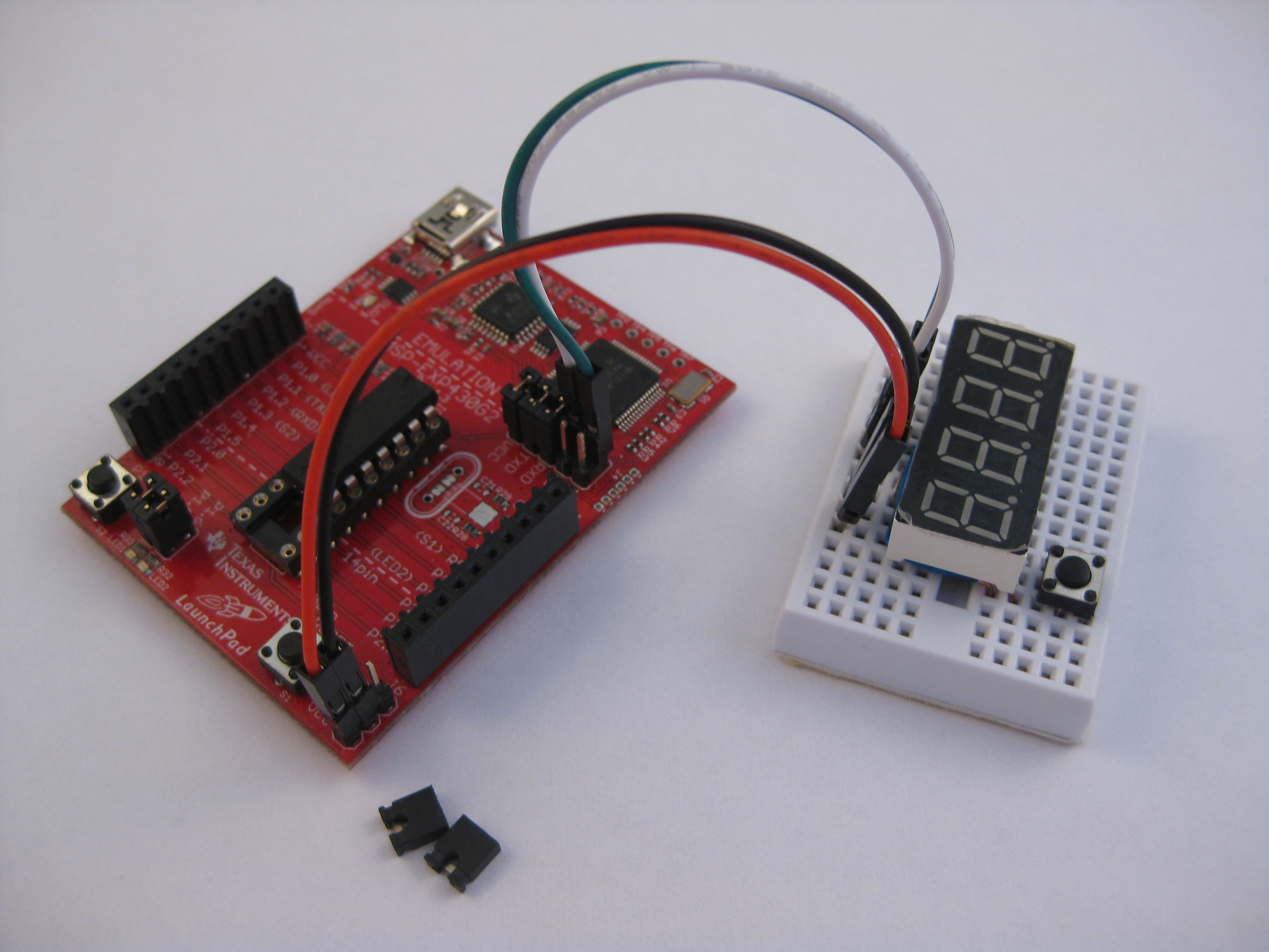
Assembled With Buzzer Alarm Option
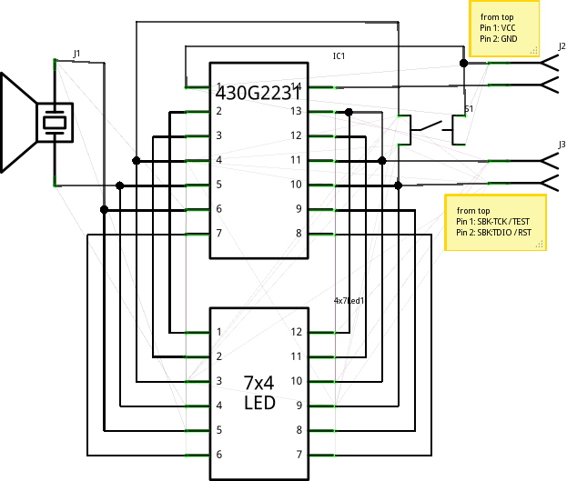
Breadboard Layout
Schematic
Source Code
Source code will be made available once the hidden Easter egg is broken.
[Nov10, 2010] easter egg uncovered by jbremnamt, see this thread in www.43oh.com
[Oct 3rd, 2010] got request for source code, so i made this stripped down source that contains everything but the Easter egg. may be there are still egg hunters out there.
[Oct 28th, 2010] replaced source code, now it can be built under CCS Windows or msp430-gcc under Linux. CCS generated firmware is not as optimized as mspgcc (or i am not optimized to configure it properly), hence the option of temperature display units has to be taken out.
You can download here
Click to download 3p4w-noegg.c
Click to download 3p4w-clock.c
source now reside in l(my github repository:https://github.com/simpleavr/old_projects/3p4w_clock)
If you got comments, questions, etc, please use forums below, i frequent both.
Forum in www.43oh.com
google groups ti launchpad here
[Nov 10, 2010] uou can now also put your comments via google friends connect at the bottom of this page, had figured out this lately.
To crack the egg (egg had been cracked, but u may build and crack it again), you may want to:
-
Built the project and “poke” around (if u have the LED module handy). there are not that many io pins to poke.
-
Use mspdebug as simulator (hard way)
chrisc@t61:~/ti/ez430/3p4w-clock> mspdebug sim
Simulation started, 0x10000 bytes of RAM

(mspdebug) prog 3p4w-clock.elf
Erasing...
Writing 128 bytes to f800...

Writing 128 bytes to ff80...
(mspdebug) reset
(mspdebug) step
( PC: f804) ( R4: 0000) ( R8: 0000) (R12: 0000)
( SP: 0280) ( R5: 0000) ( R9: 0000) (R13: 0000)
( SR: 0000) ( R6: 0000) (R10: 0000) (R14: 0000)
( R3: 0000) ( R7: 0000) (R11: 0000) (R15: 0000)
__low_level_init:
f804: b2 40 80 5a 20 01 MOV #0x5a80, &__WDTCTL
__do_copy_data:
f80a: 3f 40 02 00 MOV #0x2, R15
f80e: 0f 93 TST R15
f810: 05 24 JZ __do_clear_bss
f812: 2f 83 DECD R15
(mspdebug)
- Make use of msp430-objdump against the elf file. (easiest way, relatively)
Firmware
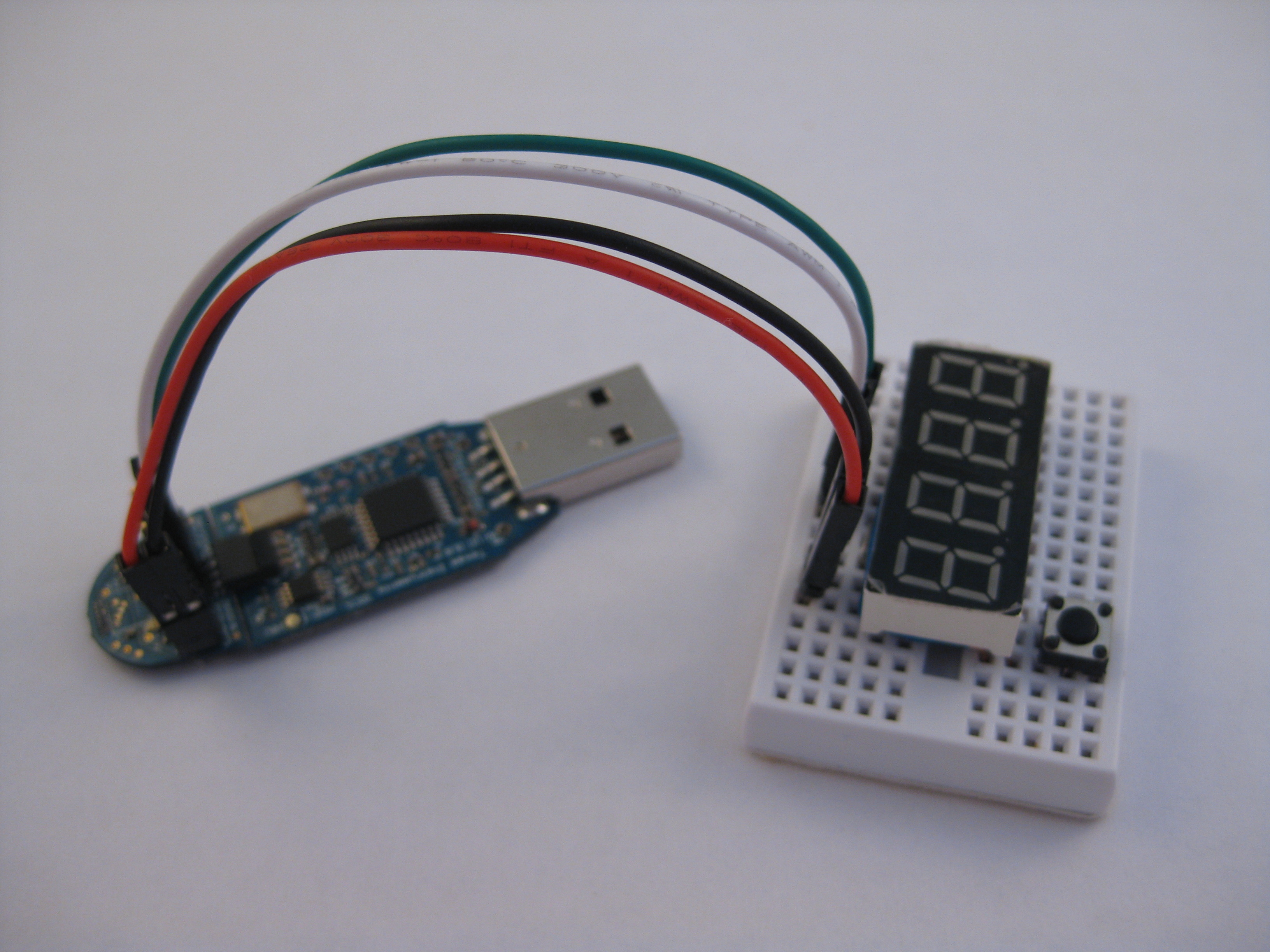
The attached firmware can be uploaded to the MCU with mspdebug. Since the project is built on a breadboard you will have to run jumpers from the programmer (ez430/rf2500/launchpad) to the breadboard. You will need to connect Gnd/Vcc + the two SBW (spy-by-wire) lines.
If you are using the RF2500 kit or the launchpad as your programmer, use the following command.
mspdebug rf2500 "prog 3p4w-clock.elf"
See also my launchpad-shield here for detail connections
If you are using the EZ430 kit as a programmer, use the following command
mspdebug -d /dev/ttyUSB0 uif "prog 3p4w-clock.elf"
see also my TI-launchbread page here for detail connections
If you are using IAR or CCS under windows, you should also be able to flash the firmware in TI txt format, i’ve used a python tool from poelzi’s OpenChronos project ( link here ) to create the firmware in TI’s txt format, which i believe can be uploaded via CCS. I’ve never tried it as i don’t use windows, if it works you may want to leave a comment on my youtube video. I am hosting this site in “google sites” and it does not allow visitor comments.
Click to download 3p4w-clock.elf
Click to download 3p4w-clock.txt
Source now reside in my github repository
Troubleshooting
Check connections, there’s not that many
Complete Construction
Enabling Buzzer Alarm
Enabling Tone Player (easter egg)