lp_8bitfft
8 Bit FFT Spectrum Analyzer
[June 2013] Originally created.
[Nov 27, 2015] sq7bti at 43oh.com had done a build w/ LED matrixes and replaced the floating point sqrt w/ a fix point one, 3 x speed improvements. Please find the improvement at the bottom of this page.
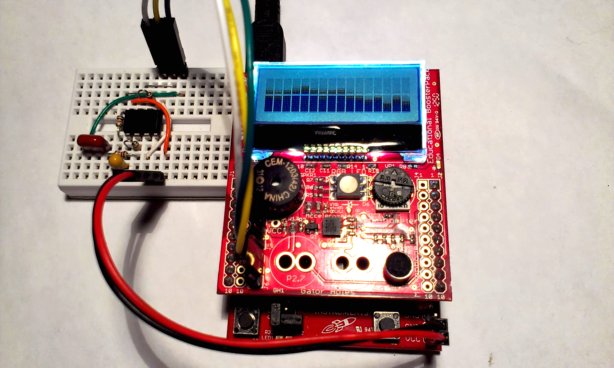
8 bit FFT Audio Spectrum Analyzer on a TI LaunchPad with Educational BoosterPack
Description
This audio spectrum analyzer is a project for the TI Launchpad (Value Line) w/ CircuitCo’s Educational BoosterPack. It is microphone based and require minimal external components. Efforts were made to maximize the use of device / features from the Educational BoosterPack.
ADC10, TimerA interrupt LPM wakeup, TimerA PWM like output, button use, integer arithmetic are used and demonstrated.
Features
- 8 bit integer FFT
- 32 samples at 250Hz separation
- shows 16 amplitudes of 250Hz, 500Hz, 750Hz,……. 5.75Khz, 6.75Khz, 7.75Khz non-linear
- partial logarithm map to show amplitudes, limited as resolution has been reduced for 8 bit FFT
- LM358 two stage mic pre-amp at 100x times 100x gain (can be improve vastly w/ better op-amps)
- utilize Educational BoosterPack; mic for input, potentiometer for pre-amp biasing
- draws power from launchpad
- square signal generator from TA0.1 toggling, good for initial testing
- TA0.1 ouput to P1.6 (io) or P2.6 (buzzer)
- P1.3 button used to cycle thru 1. no ouput, 2. P1.6 signal, 3. P2.6 buzzer
- in mode 2 and 3, both band and amplitude scales are linear
- in mode 3, signals are distorted after passing buzzer and condensor mic, especially in low frequency
Parts / Bill of Materials
This is what’s needed for this project
- a TI LaunchPad MSP430 Value Line (w/ msp430g2553 mcu)
- a CircuitCo Educational BoosterPack
- a mini breadboard or perf board for pre-amp construction
- a LM358 Dual op-amp
- 2 x 100k, 2 x 1k resistors
- 1 x 0.1uF, 1 x 10uF capacitors
- jumper wires
Schematic
TI LaunchPad + Educational BoosterPack
Below shows IO pins used
Physical hookup (jumpers) is required for the pre-amp circuit only
The LCD and buzzer are connected via the Educational BoosterPack
---------------
/|\| XIN|-
| | |
--|RST XOUT|-
| |
| P1.5|--> IO (Booster lcd clock)
| P1.7|--> IO (Booster lcd data)
| P2.3|--> IO (Booster lcd data/command select)
| |
| P1.4|<-- ADC4 (from microphone pre-amp)
| |
| P1.3|<-- Launchpad Button
| P1.6|--> TA0.1 (Launchpad green LED, test signal)
| P2.6|--> TA0.1 (Booster Buzzer, audio test signal)
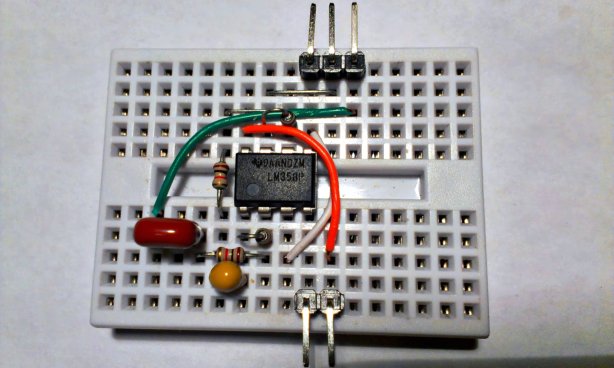
The op-amp microphone amplifier can be constructed on breadboard or pref board
LM358 Dual Op-Amp, GBW @0.7Mhz, each stage @x100 gain, bandwidth is 7Khz
o------------------------------o
_|. |
___ 10uF |
+ | --------------- |
o-1|----. Vcc|8 |
|. | ^ .---|7--o-------|-----o (A)
100k| | | / \ ^ | |. |.
|_| | /__+\ / \ | | |100k | |1k
0.1u | | | | /__+\ | |_| |_|
(B) o--||--[ 1k ]--o-2|---+ | | | | | |
(C) o-------------o---3|-----+ +-|--|6--o-------o
| 4|Gnd +--|5----o
| --------------- |
| |
o--------------------------o
Points A, B and C + power need to be connected to the Launchpad and Booster
(A) to P1.4 EduBoost Mic jumper middle pin
(B) to Condenser Mic, EduBoost Mic Jumper top pin
(C) to Potentiometer, EduBooster Potentiometer Jumper top pin
(+) connect Gnd + Vcc to Launchpad
CircuitCo Educational BoosterPack
The Educational BoosterPack is designed to work w/ TI Launchpad and features the following;
- Back-lit Character LCD Display
- Dial analog potentiometer
- 3-Axis analog accelerometer
- RGB LED
- Buzzer
- Microphone
Details can be found here
There is also a review on this Booster that contains a lot of information including library and example codes on driving various elements of the BoosterPack. http://embeddedcomputing.weebly.com/educational-boosterpack.html
LCD Driving
The LCD module use a SPI like interface. This is control by the firmware via the clock, data and a data select pin. The command set can be found here from this supplier. We are doing the SPI bit-bang style for simplicy and there is no need for speed being character based.
For this project we download a set of 8 custom font characters to the LCD module. These characters will graphically present the amplitude of different frequency bands.
Sound Capture
Sound is capture via the on board condenser microphone on the Educational BoosterPack. As microphone signals are small, we need to amplify it to a level that the msp430 ADC10 can use w/ a reasonable resolution. I had used a two-stage op-amp amplifier for this purpose.
The op-amp amplifier is consist of two stages, each w/ a about 100x gain. I had chosen to use a LM358 as it is a very common part and it works w/ 3.6V. It does have its limitations. The gain bandwidth being only 0.7Mhz means that for our gain of 100x, we can only guarantee it would work nicely (i.e. maintain the gain we want) under 7Khz. (0.7Mhz / 100). This is also why we need to do it in two stages.
Originally I intend to make this spectrum analyzer measure up to 16-20Khz, but in the end I found about 8Khz is good enough to show music. This can be changed by replacing the LM358 w/ something of audio-rated and changing the sampling rate. Just look for the gain bandwidth of the op-amps you choose.
Sampling and FFT
The FFT function used is the “fix_fft.c” code that many projects had adopted, it has been floating around in the internet for some years. I had tried a 16 bit version and a 8 bit version. Eventually I settled for the 8 bit version as for my purpose, I did not see a major advance on the 16 bit version.
I do not have a good understanding of the FFT mechanism except that it’s a time domain to frequency domain conversion. That means the rate (time) of the sound samples, after feeding to the FFT calculation function, will affect the frequency of the amplitude I am getting as a result. So by adjusting the rate to sample sound, I can determine the frequency band as the result.
TimerA 0 CCR0 is used to keep the sampling time. We first determine the counts we need to achieve the band frequency (corresponds to our DCO clock rate of 16Mhz). i.e. TA0CCR0 set to (16000/(BAND_FREQ_KHZ*2))-1; where BAND_FREQ_KHZ is 8 for me. It can be changed if you got a better op-amp and / or wants it be different.
Frequency Bands and Amplitude Scaling
The firmware process 32 bands at one sweep, and the capture timing produces 250Hz separation between these banks. Our LCD is of 16 columns and will only display 16 bands / amplitudes. Instead of displaying one every two bands, a non-linear frequency band list is used to show the more dynamic frequency bands (in terms of music). The list is of 250Hz gaps at the low end, 500Hz gaps in the middle bands and 2Khz bands in the highs.
The amplitude of individual bands are scaled down to 15 levels, which are represented by the number of horizontal ‘bars’ on the LCD display. They are represented by custom characters. A full amplitude will occupy both the top and bottom line of the same character position on the LCD display. The amplitude levels are scaled down via a non-linear map that translates FFT results into one of the 15 bars. A sort-of logarithmic scaling is used as it best represent our perception of sound levels.
Building the project
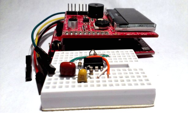
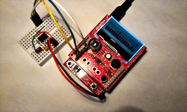
I would recommend building the project on a breadboard initially. This is because you will be able to change many parameters on the breadboard to your likings. You may transfer later on to a PCB or pref-board for more permanent use once you are satisfied w/ your tests. You can use the layout as photographed below as a start.
The photo below shows the connection required to attach the op-amp circuit to the educational boosterpack and launchpad. Five jumper wires are used.
I had used both mspgcc and ccs compiler to build the firmware but had only tested the gcc version. The compile / link command is as such, it is important to note that we need to do a “-lm” to link to the math library
msp430-gcc -Os -Wall -ffunction-sections -fdata-sections -fno-inline-small-functions -Wl,-Map=gcc/lp_8bitfft.map,--cref -Wl,--relax -Wl,--gc-sections -mmcu=msp430g2553 -c fix_fft.c -o gcc/fix_fft.o
msp430-gcc -Os -Wall -ffunction-sections -fdata-sections -fno-inline-small-functions -Wl,-Map=gcc/lp_8bitfft.map,--cref -Wl,--relax -Wl,--gc-sections -mmcu=msp430g2553 -c lp_8bitfft.c -o gcc/lp_8bitfft.o

msp430-gcc -Os -Wall -ffunction-sections -fdata-sections -fno-inline-small-functions -Wl,-Map=gcc/lp_8bitfft.map,--cref -Wl,--relax -Wl,--gc-sections -mmcu=msp430g2553 -o gcc/lp_8bitfft.elf gcc/fix_fft.o gcc/lp_8bitfft.o -lm
To simplify testing / trouble-shooting, this project includes a square wave signal generator. Pressing the launchpad tactile button at P1.3 will cycle through 3 modes of operation state. Mode 0 is off, Mode 1 is P1.6 output, Mode 2 is P2.6 output (to buzzer).
If you are to test the Spectrum Display before finishing the op-amp circuit, you can select Mode 1 and jumper short P1.6 (feed it from the launchpad green LED header) to P1.4 (point A from the schematic). The firmware will generate a linear set of frequencies to be observed / processed by the FFT logic. Mode 2 is the same as Mode 1 except the output pin is a pin to the buzzer driver, which produce audible sound instead of a pin-out signal. In both Mode 1 and Mode 2, the frequency band and the amplitude are switched to show ‘linear’.
For Mode 2 frequency out, you need to have the op-amp circuit finished and attached for testing. What you will observe will be far from ideal, as I found out the buzzer only behave well at 2Khz, most other bands are very distorted and higher frequency does not response well.
For the op-amp circuit, it is a very simple and standard inverting amplifier setup on both stages. You can just follow the ascii-art schematic and / or the photo to have it built. There are 3 points in the op-map circuit that need to be connected, point B is connecting to the condenser mic as the op-amp input, point A is the amplified output that needs to go back to P1.4 / ADC channel 4 input of the MCU. Point C is connecting to the Educational BoosterPack’s on board potentiometer, we use it to bias our op-amp input.
The gains of both stages had been set to about 100 and they can be altered by changing the 100k and 1k resistors as it is approximately 100k/1k. You can also replace the LM358 op-amp with others, just make sure the gain bandwidth of your op-amp can work nicely at the maximum frequency that you want to capture (along w/ the gain you want).
Application Demonstration
Comment from a builder sq7bti at 43oh.com
I noticed that the only floating point operation that your code was using is a square root operation in line 257. Once I added a fixed-point square root routine, linking with math lib is not necessary anymore - spared a lot of flash space. The fixed-point routine is also 3 times faster than mathlib floating point one: 50us vs 150us
unsigned char sqrt16(unsigned short a) {
        unsigned short rem = 0, root = 0;
        int i;
        for(i = 0; i < 8; ++i) {
                root <<= 1;
                rem = ((rem << 2) + (a >> 14));
                a <<= 2;
                ++root;

                if(root <= rem) {
                        rem -= root;
                        ++root;
                } else {
                        --root;
                }
        }
        return (unsigned char)(root >> 1);
}
Video of sq7bti’s build