breadboard_collections
5P4W Clock
[October 2015] Originally created.
UNDER CONSTRUCTION and source code not yet available
5 Parts 4 Wires Clock. Digital clock built with minimal components and wirings.
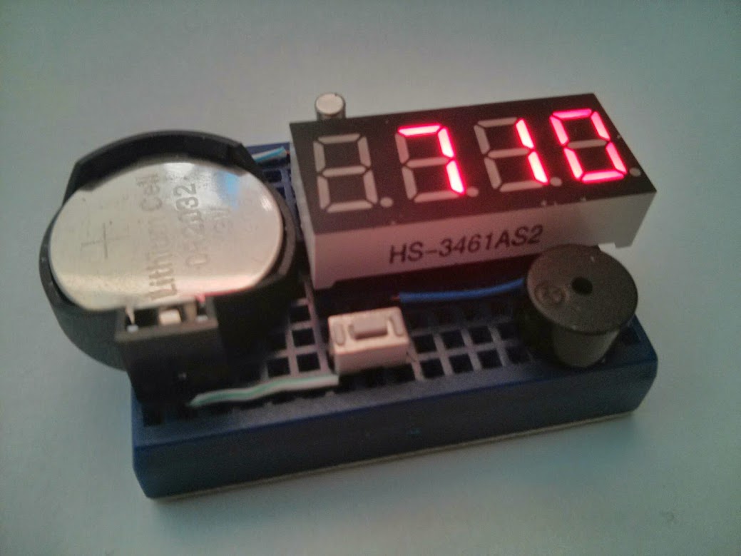
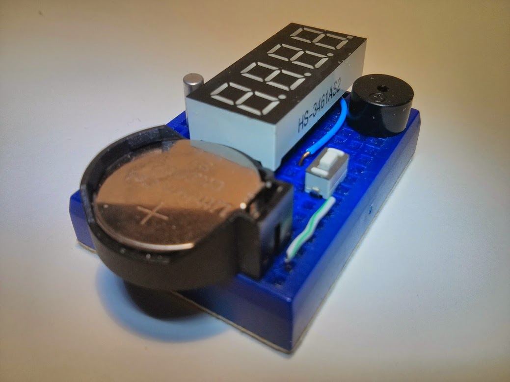
All components on a mini breadboard
Description
This is a redo of an older project 3p4w clock. The 3p4w clock is one of my attempts to create the most simple MCU based clock project. It was based on a 14 pin MSP430G2231 device from the then $4.30 TI launchpad development system.
Since then the TI launchpad G2 had changed and instead includes 20 pin devices like MSP430G2553 and MSP430G2452. I had also find ways to incorporate use of clock crystals and thus improve the accuracy of the project.
The 5p4w clock design inherits the LED multiplexing design of the 3p4w clock. The additional parts making it a 5p over 3p is the 32Khz clock crystal being added and I also count the battery holder as another part. This clock also carries the optional alarm (auto detect) and houses the original easter-egg application.
buzzer is optional for alarm and timer
Features
- Minimal components, 3 parts (4 parts if you need alarm)
- 4 jumper wires on a mini breadboard
- Battery operated from 3V
- Use of 32Khz clock crystal to keep time, power-down sleep mode (LPM3) takes less than 1uA power
- Ambient temperature read in metric and imperial units (MCU permitting)
- Optional alarm if you connects a buzzer (auto-detect), this will make the 6p4w clock
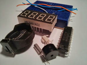
Parts list
- 170 tie point mini breadboard
- MSP430G2412 (or other G/F series dip 20 pin devices w/ 4k flash)
- 4 digits common cathode 7 segment LED display
- Tactile button
- 32Khz clock crystal
- 9mm passive buzzer
- CR2032 button cell holder (battery not included)
- all parts present
Application Notes
- If buzzer is connected, firmware allows for alarm setting and usage
- Single button press toggles thru hours + minutes, alarm on/off + seconds, and sleep modes
- Long press enters setup mode, subsequent long press rotates thru menu
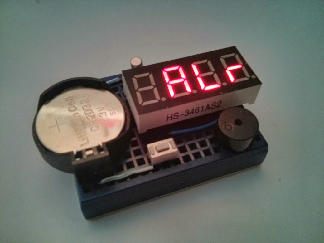
- Menu items cycles thru SEt, ALr, Cnt, bri
- In ‘SEt’ time setup mode, short press enters setup
- Once in setup, short press toggle digit values (hours, minutes) and long press confirms choice of 12H or 24H display
- Likewise in ‘ALr’ alarm setup mode, hours and minutes can be entered
- Choice of alarm On or oFF
- ‘Cnt’ selects the kitchen timer function, enter minutes and seconds, long press to confirm and starts count down
- When in sleep mode, MCU goes in power down mode, consuming less than 1uA of power, watchdog timer is set so that system wakes-up every 1/4 second. This is maintain by the 32Khz clock crystal
- In ‘bri’ dimmer setting, short presses cycles through available brightness levels, long press confirms setting
- led segment multiplexing includes time delays to compensate for brightness differences for individual digits. ie. when displaying a digit ‘8’ we stay longer than displaying a digit ‘1’ to compensate for the loss of brightness when driving multiple segments.
- menu selected to set up alarm
Breadboard Layout
   +=====================================================+
   |  .  o-----(W3)-----o  .  .  .  .  .  .  .  .  .  .  | XT 32Khz clock crystal
   |  . (-) .  .  .  .  .  oXTo  .  o---(W1)-----------+ | W1 joins IO pin to a2
   |                \   .  .  .  o---(w2)----------o  .| | W2 joins CK pin to b3
   |                 :  .  .  .  .  .  .  .  .  .  .  .| | W3, W4 battery power to MCU
   |                 :  ---+--+-(0)-A--F-(1)(2)-B--+- .| |
   | Battery Holder  : |- b6 b7 CK IO a7 a6 b5 b4 b3|  | |
   |                 : |+ a0 a1 a2 a3 a4 a5 b0 b1 b2|  | |
   |                 :  ---+--+--+--+--+--+--+--+--+  .| |
   |                 :  .  .  .  E  D (.) C  G (3) .  .| |
   |                /.  .  .  .  .  .  .  .  .  .  .  .| |
   |  . (+) .  .  .  .  .  .  .  x  .  x  .  +=BZR=o  .| | BzR buzzer, observe + sign
   |  .  o------(W4)----o=BTN=o------------------------+ | BTN button
   +=====================================================+
                                 +=BZR=o (easter egg buzzer placement)
Schematic
                            MSP430G2xxx
                         -----------------
                        |            RESET|----------+
          +-------------|TEST             |          |
          |             |                 |          |        /|\
          |    SEG G <--|P2.0         P1.0|-->       |    _|_  |
          |  DIGIT 3 <--|P2.1         P1.1|--> SEG A +---o   o-- button
          |          <--|P2.2         P1.2|--> SEG E
          +- DIGIT 0 <--|P2.3         P1.3|--> SEG D
               SEG B <--|P2.4         P1.4|--> SEG H
             DIGIT 2 <--|P2.5         P1.5|--> SEG C
      32Khz /-----------|P2.6(XIN)    P1.6|--> DIGIT 1
    Crystal \-----------|P2.7(XOUT)   P1.7|--> SEG F
                        |                 |
Assembling
- Follow breadboard layout and place jumper wire on mini breadboard
- Place MSP430G2412 on breadboard
- Place Tactile Button
- Place Buzzer
- Place Battery Holder
- Finally place 7 Segment Led Module on top of mcu
Source code
Source code usually resides in my github repositories.
For this particular project, the single C source file 5p4wclock.c is bundled in my breadboard collections repository. You just need 5p4wclock.c